


111
OPERATING PROCEDURE
PHOTOS & ILLUSTRATION
PUZ-A24/30/36NHA2 PUZ-A24/30/36NHA2-BS
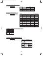
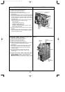
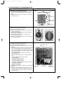
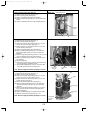
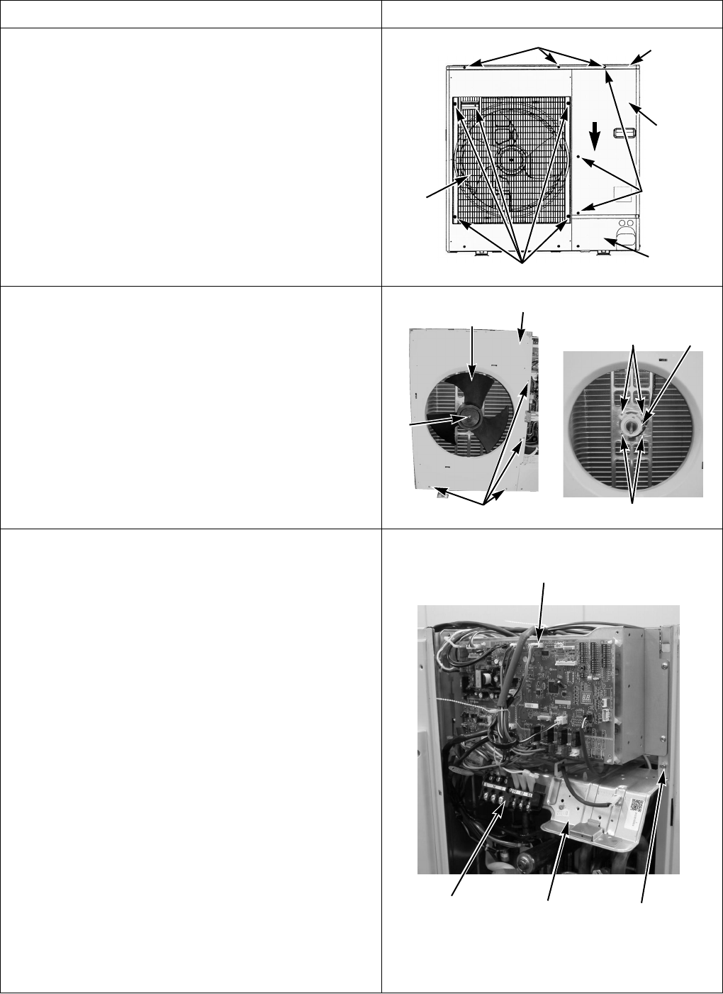
1. Removing the service panel and top panel
(1) Remove 3 service panel fixing screws (5 ✕ 10) and slide
the hook on the right downward to remove the service
panel.
(2) Remove screws (3 for front, 3 for rear/5 ✕ 10) of the top
panel and remove it.
Figure 1
Top panel fixing screws
Top panel
Service panel
fixing screws
Service panel
Grille fixing screws
Fan grille
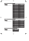
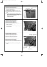
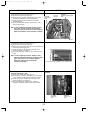
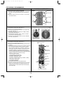
2. Removing the fan motor (MF1)
(1) Remove the service panel. (See figure 1.)
(2) Remove the top panel. (See figure 1.)
(3) Remove 5 fan grille fixing screws (5 ✕ 10) to detach the
fan grille. (See figure 1.)
(4) Remove a nut (for right handed screw of M6) to detach
the propeller. (See photo 1.)
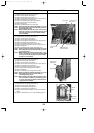
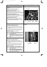
(5) Disconnect the connector CNF1 on controller circuit
board in electrical parts box.
(6) Remove 4 fan motor fixing screws (5 ✕ 25) to detach the
fan motor. (See photo 2.)
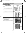
Photo 3
Photo 1
Propeller
Front panel
Front panel fixing screws
Nut
Photo 2
Slide
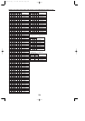
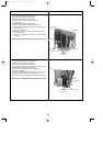
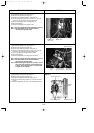
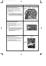
3. Removing the electrical parts box
(1) Remove the service panel. (See figure 1.)
(2) Remove the top panel. (See figure 1.)
(3) Disconnect the indoor/outdoor connecting wire from termi-
nal block.
(4)
Remove all the following connectors from controller circuit board,
fan motor, linear expansion valve, thermistor<Outdoor
pipe>, thermistor<Discharge>, thermistor<Outdoor 2-phase
pipe>, thermistor<Outdoor>, high pressure switch, 4-way
valve and bypass valve.
Then remove a screw (4 ✕ 8) from the valve bed to
remove the lead wire.
Pull out the disconnected wire from the electrical parts
box.
<Diagram symbol in the connector housing>
• Fan motor (CNF1)
• Linear expansion valve (LEV-A)
• Thermistor <Outdoor pipe> (TH3)
• Thermistor <Discharge> (TH4)
• Thermistor <Outdoor 2-phase pipe, Outdoor> (TH6/7)
• High pressure switch (63H)
• 4-way valve coil (21S4)
• Bypass valve coil (SV2)
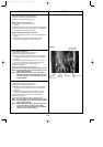
(5) Remove the terminal cover and disconnect the compressor
lead wire.
(6) Remove an electrical parts box fixing screw (4 ✕ 10) and
detach the electrical parts box by pulling it upward. The
electrical parts box is fixed with 2 hooks on the left and 1
hook on the right.
Cover panel
Electrical parts box
Controller circuit board
(C.B.)
Electrical parts
box fixing screw
Terminal block
(TB1)
Fan motor fixing screws
Fan
motor
Fan motor fixing screws
OCH429--4.qxp 07.11.20 9:20 AM Page 111