


64
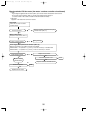
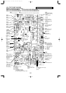
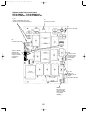
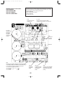
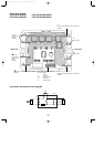
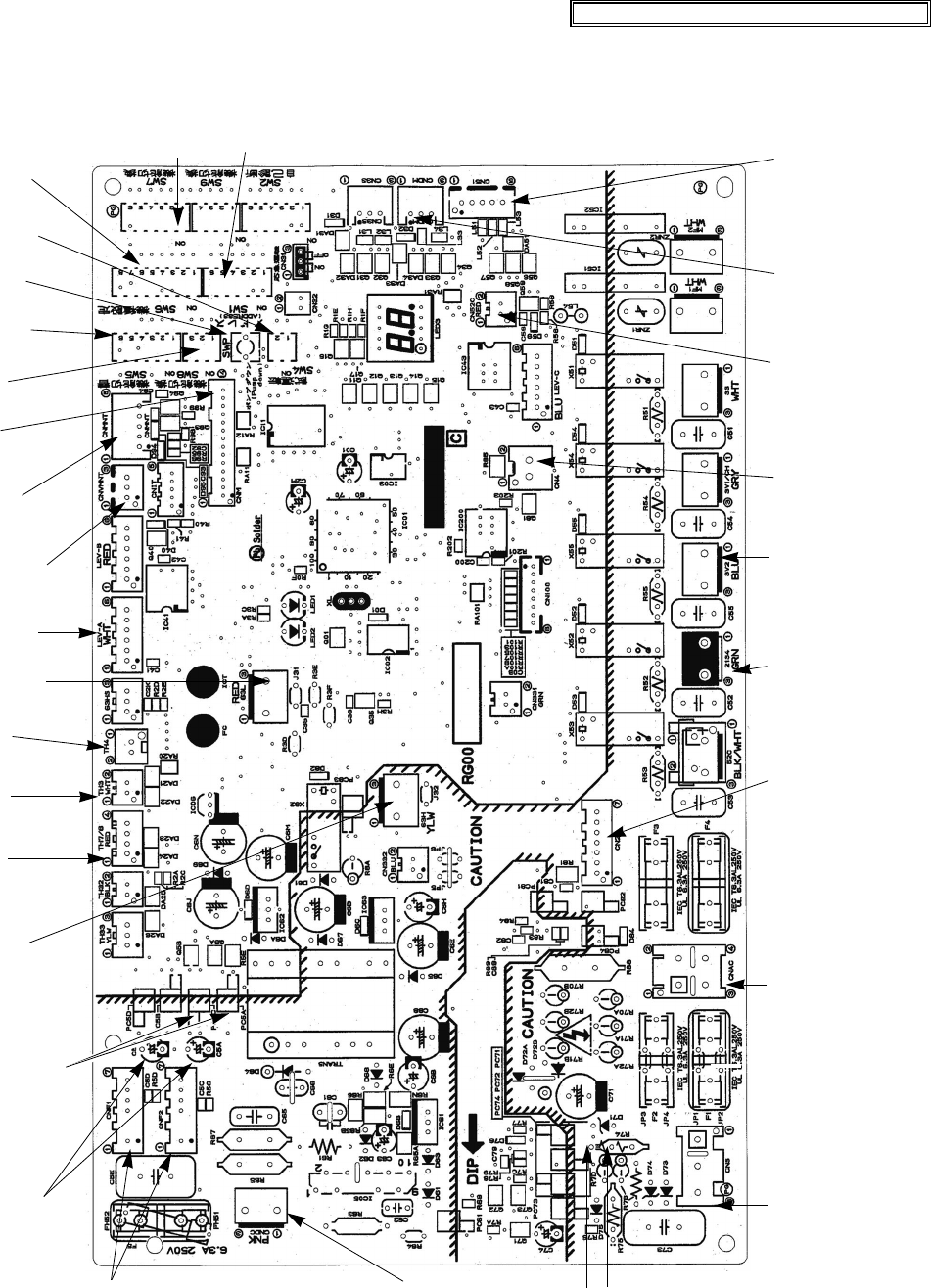
10-9. TEST POINT DIAGRAM
Outdoor controller circuit board
PUZ-A18/24/30/36/42NHA2 PUZ-A18/24/30/36/42NHA2-BS
PUY-A12/18/24/30/36/42NHA2 PUY-A12/18/24/30/36/42NHA2-BS
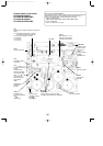
<CAUTION> TEST POINT1 is high voltage.
Communication power supply
D71 Voltage
24V DC
CNS
S1-S2:A208/230V AC
CNAC
2 to 4:
Power supply for out-
door controller circuit
board (208V-230V AC)
1 to 3:
Power supply for indoor
and outdoor unit con-
nection wire
(208/230V AC)
CNF1, CNF2
Connect to the fan motor
1-4: 280V DC
5-4: 15V DC
6-4: 0-6.5V DC
7-4: 15V DC(When stopped)
7.5V DC(When operated)
(0V-15V pulse)(CNF2 is only for A42)
21S4
Four-way valve
<PUZ only>
63H
High pressure
switch
SV2
Bypass valve
<A24/30/36 only>
CN4
Transmission to out-
door power circuit
board (CN4)
SW4
Test operation
SW6
Model select
SW5
Function switch
SW1
Forced defrost, detect history record reset, refrigerant address
CNDM
1 to 2:
Input of low-level
sound priority mode
1 to 3:
Input of external con-
tact point
TH4
Thermistor
<Discharge>
TH3
Thermistor
<Outdoor pipe>
TH7/6
Thermistor
<Outdoor/
2-phase pipe>
CNDC
280V DC (1+, 3-)
(Outdoor power circuit
board)
+ -
VFG
(TEST POINT 4)
(Voltage between
right pins of PC5C
and PC5D, pin 3
and pin 4)
(Same as
(CNF1
7(+)-4(-))
VSP
(TEST POINT 3)
(Voltage between pins
of C5A, C5B):
DC 0V (when stopped),
DC 1– 6.5V
(when operated)
SW7
Demand control setting
CN51
External signal output
• Compressor operating
signal
• Abnormal signal
LEV-A
Linear expansion
valve
SWP
Pump down
SW8
Wiring replace
CNM
Connect to A control
service tool
CNMNT
Connect to
M-NET adapter(CN5)
CNVMNT
Connect to
M-NET adapter(CND)
CN2
Connect to the outdoor
power circuit board (CN2)
1-5: Reception from
power circuit board
2-5: Zero cross signal
(0-5V DC)
3,4:
18V DC
6-5: 16V DC
7-5: 16V DC
CN52C
(Connect to the noise
filter circuit board
(CN52C))
63L
Low pressure switch
<A42 only>
OCH429--3.qxp 07.11.20 9:19 AM Page 64