


28
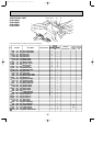
OPERATING PROCEDURE PHOTOS
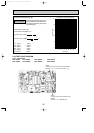
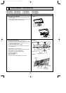
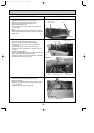
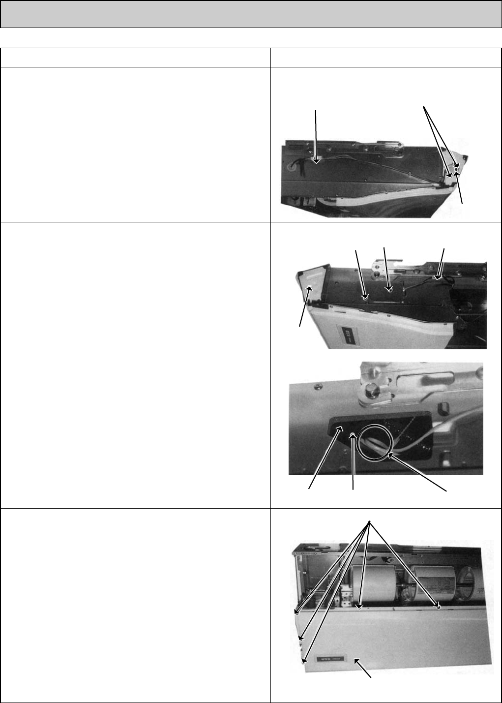
6. Removing the vane motor <MV>
(1) Remove the air intake grille. (See the figure 1)
(2) Remove the left side panel. (See the figure 3)
(3) Remove the relay connector of vane motor.
(4) Remove the electrical box.
(5) Remove the screws of vane motor, then remove vane
motor <MV>.
(Note)
Connect the lead wires and connectors properly and place
them in the proper position so that the wires are not pinched
by other parts.
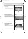
8. Removing the Under panel
(1) Remove the air intake grille. (See the figure 1)
(2) Remove the beam.
(3) Remove the side panel (right and left). (See the figure 3)
(4) Remove the 9 screws of the under panel, then remove
the under panel.
w Weight of the under panel : Approx. 2kg.
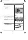
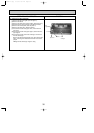
7. Removing the Indoor coil thermistor <TH2/TH5>
(1) Remove the air intake grille. (See the figure 1)
(2) Remove the right side panel. (See the figure 3)
(3) Remove the relay connector of the pipe thermistor
<TH2/TH5>.
(4) Remove the screw, and remove the check panel.
(5) Extract the indoor coil thermistor <TH2/TH5> from the
holder.
<Caution for the installation>
There is a possibility for the short circuit when connector gets
wet by water through the thermistor lead wire.
Therefore, lead wire of the indoor coil thermistor <TH2/TH5>
should be tied as shown in the photo 6.
Photo 4
Photo 7
Screw
Screws
Relay connector of
the vane motor
Vane motor
Under panel
Photo 5
Photo 6
Screw
Hold Indoor coil thermistor Clamp
Check
panel
Relay connector of
the pipe thermistor
Left side
panel
OC368B--1.qxp 07.6.20 1:01 PM Page 28