


24
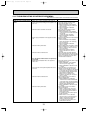
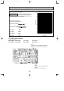
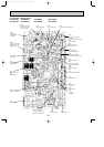
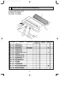
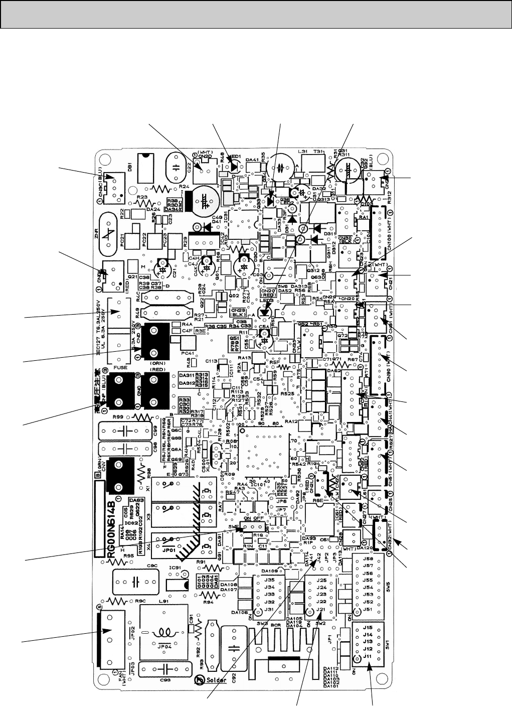
10-6-2. Indoor controller board
PCA-A24GA PCA-A30GA PCA-A36GA PCA-A42GA
PCA-A24GA1 PCA-A30GA1 PCA-A36GA1 PCA-A42GA1
CN2D
Connect to the indoor
power board (CN2S)
(12.5~13.7V DC)
CNDK
Connect to the indoor
power board (CNSK)
(208/230V AC)
FUSE
(6.3 A 250 V)
CN22
Connect to the terminal
block(TB5)
(Remote controller connecting
wire)
(10.4~14.6V DC)
CN21
Pipe temperature
thermistor/Liquid (TH2)
CN20
Room temperature
thermistor (TH1)
CN41
Connector (HA terminal-A)
CN6V
Vane motor output
(MV)
CN90
Connect to the wireless
remote controller board
(CNB)
CN31
Drain sensor (DS)
CN51
Centrally control
CN29
Condenser/evaporator
temperature thermistor (TH5)
CN24
Heater output
(12V DC)
SW1
Model setting
SW2
Capacity setting
SWE
Emergency operation
LED1
Power supply (I.B)
LED2
Power supply (R.B)
LED3
Transmission (Indoor/outdoor)
CN3C
Transmission
(Indoor/outdoor)
(0~24V DC)
FAN
Fan motor output
Jumper wire J41, J42
Pair number setting with
wireless remote controller
CND
Power supply input
(208/230V AC)
CNP
Drain-pump output
(DP)
(208/230V AC)
CN2L
Connector
(LOSSNAY)
CN32
Remote switch
OC368B--1.qxp 07.6.20 1:01 PM Page 24