


22
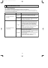
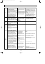
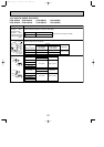
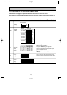
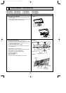
10-5. HOW TO CHECK THE PARTS
PCA-A24GA PCA-A30GA PCA-A36GA PCA-A42GA
PCA-A24GA1 PCA-A30GA1 PCA-A36GA1 PCA-A42GA1
1
1
2
2
3
3
Red
White
Black
Relay connector
Protector
4
5
2
361
Orange
Red
Pink
Yellow Brown Blue
M
4
2
5
31
Pink
Orange
Red
Yellow Blue
M
OFF:130i5:
ON :80i20:
Parts name Check points
Disconnect the connector then measure the resistance using a tester.
(At the ambient temperature 10:(50˚F)~30:(86˚F))
(Refer to the next pege for a detail.)
Room temperature
thermistor (TH1)
Pipe temperature
thermistor (TH2)
Condenser/evaporator
temperature thermistor
(TH5)
Normal
4.3k"~9.6k"
Abnormal
Open or short
Measure the resistance between the terminals using a tester.
(Winding temperature 20:(68˚F))
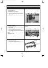
Fan motor (MF)
Abnormal
Open or short
Motor terminal
or
Relay connector
60.8"
55.1"
41.1"
54.3"
Normal
Open or short
Abnormal
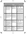
Connector
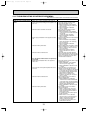
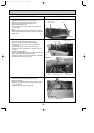
PCA-A24·30GA
(1)
140~160"
Normal
Open or short
Abnormal
Connector
PCA-A36·42GA
(1)
Normal
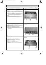
Vane motor (MV)
140~160"
Red–Yellow
Red–Blue
Red–Blue
Red–Pink
Brown–Yellow
Brown–Blue
Red–Orange
Red–Pink
Red–Black
White–Black
PCA-A24GA
(1)
PCA-A30GA(1)
PCA-A36GA(1)
PCA-A42GA(1)
OC368B--1.qxp 07.6.20 1:01 PM Page 22