


26
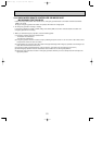
DISASSEMBLY PROCEDURE
11
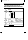
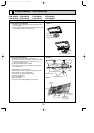
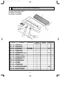
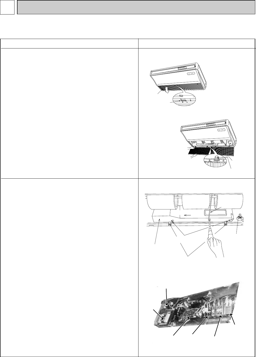
1. Removing the air intake grille
(1) Slide the intake grille holding 2 knobs backward to open
the intake grille.
(2) When the intake grille left open, push the stoppers on the
rear 2 hinges to pull out the intake grille.
OPERATING PROCEDURE PHOTOS & ILLUSTRATIONS
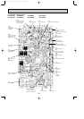
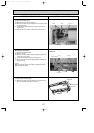
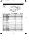
2. Removing the electrical box
(1) Remove the air intake grille. (See the figure 1)
(2) Remove the screw from the beam and remove the beam.
(3) Remove the screws from the electrical cover, and
remove the electrical cover.
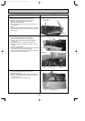
(4) Disconnect CN6V, CN21 and CN29.
(5) Remove the screws from the electrical box and pull out
the electrical box.
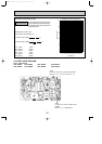
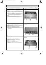
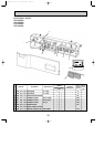
<Electrical parts in the electrical box>
Terminal block (for indoor / outdoor connecting line)<TB4>
Terminal block (for power supply)<TB2>
Terminal block (for remote controller)<TB5>
Fan motor capacitor<C>
Indoor control board<I.B>
Power board<P.B>
(There might not be TB2 depending on the model.)
Figure 1
Figure 2
Photo 1
slide
Intake grille
Intake grille
Holding knobs
Hinges
Pull out the intake grille
Electrical cover
Screw(electrical cover)
Screw(electrical box)
Slide to the left
Beam
Clamp
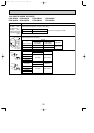
PCA-A24GA PCA-A30GA PCA-A36GA PCA-A42GA
PCA-A24GA1 PCA-A30GA1 PCA-A36GA1 PCA-A42GA1
Fan motor
capacitor
Power board
Indoor control
board
Terminal block
(power supply)
Terminal block
(Indoor / outdoor
connecting wire)
Terminal block
(remote control)
OC368B--1.qxp 07.6.20 1:01 PM Page 26