5. INSPECTION AND MAINTENANCE
5
−
19
(b) Troubleshooting output circuits
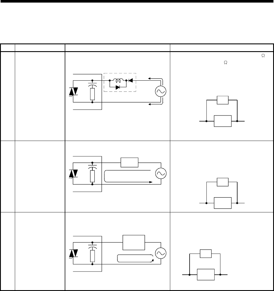
Table 5.8 describes problems and corrective actions for output circuits.
Table 5.8 Troubleshooting Output Circuits
Symptom Cause Corrective Action
Example 1
Overvoltage applied to
load when output turns
OFF
•
If load is internally half-wave rectified
(some solenoids are like this)
A1SY22
Output module
Load
D1
[1]
[2]
•
With polarity (1), C is charged. With polarity (2),
the C charge voltage plus the power supply
voltage is applied across D1. Max. voltage is
approx. 2.2V.
•
Connect a resistor between several tens k
and several hundreds k across the load.
(This method causes no problems with output
terminals but can lead to deterioration or burn-
out of load internal diodes.)
Resistor
Load
Example 2
Load does not turn
OFF
(Triac output)
•
Leak current due to internal surge suppresor.
Output module
Load
Leak current
A1SY22
•
Connect a resistor across the load.
(If long wiring exists between the output card
and the load, leak currents also arise due to
wiring capacity.)
Resistor
Load
Example 3
Time period fluctuates
when load is a CR
timer
(Triac output)
A1SY22
Output module
CR timer
Leak current
•
Drive a relay and use the relay contacts to drive
the CR timer.
(See note attached to Example 1, as some
timers are half-wave rectified internally.)
Resistor
CR timer
Calculate resistor
constant from load.


