


Net Safety Monitoring Inc
TABLE OF CONTENTS
Important Information
Warranty
Contact Information
Introduction . . . . . . . . . . . . . . . . . . . . . . . . . . . . . . . . . . . . . . . . . . . . .1
The Product ...................................................................................................... 1
The Sensor ............................................................................................................. 1
The Controller ....................................................................................................... 1
The Manual ........................................................................................................... 1
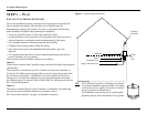
Step 1 — Plan . . . . . . . . . . . . . . . . . . . . . . . . . . . . . . . . . . . . . . . . . . . .2
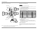
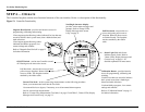
Locate Controller/Sensor ................................................................................. 2
Figure 1: Locate Sensor/Controller .......................................................................... 2
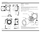
Figure 2: Dimensional Drawings ............................................................................. 3
Step 2 — Install . . . . . . . . . . . . . . . . . . . . . . . . . . . . . . . . . . . . . . . . . .3
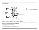
Unpack ............................................................................................................. 3
Figure 3: Components .............................................................................................. 3
Mount .................................................................................................................... 4
Step 3 — Wire . . . . . . . . . . . . . . . . . . . . . . . . . . . . . . . . . . . . . . . . . . .4
Field Installation .............................................................................................. 4
Seal ................................................................................................................... 4
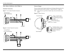
Connecting Wires .................................................................................................. 4
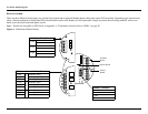
Board Assembly .................................................................................................... 5
Figure 4: Millennium Module Boards ...................................................................... 5
Figure 5: Wiring—Controller and Sensor ................................................................ 6
Sensor and Controller ...................................................................................... 6
Table 1: Controller/Sensor Connections .................................................................. 6
RS-485 Communication ........................................................................................ 6
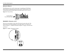
Sensor Separation ............................................................................................ 7
Figure 6: Wiring—Sensor Separation ...................................................................... 7
Non-Isolated/Isolated Wiring .......................................................................... 8
Terminal Connection ............................................................................................. 8
Figure 7: Non-isolated Terminal Connection .......................................................... 8
Figure 8: Isolated Terminal Connection .................................................................. 8
Current Output ....................................................................................................... 8
Figure 9: Jumper Positions ....................................................................................... 8
Remote Reset ................................................................................................... 9
Figure 10: Remote Reset ......................................................................................... 9
MODBUS Termination ....................................................................................9
Figure 11: Modbus Termination Jumpers ................................................................9
Step 4 — Operate . . . . . . . . . . . . . . . . . . . . . . . . . . . . . . . . . . . . . . . 10
Figure 12: Controller Functionality ........................................................................10
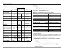
Table 2: Status LEDs, Display Messages and Current Loop .................................11
RTU Registers .....................................................................................................11
Table 3: RTU Status Register (40002) Read Only (Binary) ..................................11
Calibration Button ...............................................................................................11
Magnetic Reed Switch .........................................................................................12
Power Up .............................................................................................................12
Current Loop Measurement (Test Jacks) .............................................................12
Status LED ...........................................................................................................12
The Main Menu ..............................................................................................12
Accessing the Main Menu ...................................................................................12
Main Menu Functionality ....................................................................................12
Step 5 — Calibrate . . . . . . . . . . . . . . . . . . . . . . . . . . . . . . . . . . . . . . 13
Calibration Procedure .....................................................................................13
Calibration Procedure ..........................................................................................13
Figure 13: Calibration Procedure ...........................................................................13
Calibration Failure .........................................................................................14
Step 6 — Monitor . . . . . . . . . . . . . . . . . . . . . . . . . . . . . . . . . . . . . . . 14
Review Relay Settings ....................................................................................14
Relay Options .................................................................................................15
Table 4: Default Relay Settings ..............................................................................15
Setting Relay Options ..........................................................................................15
Modbus Options .............................................................................................16
Node Address ......................................................................................................16
Baud Rate ............................................................................................................16
Enter Restricted Menu ....................................................................................16
Set Low Power Options - Optional ......................................................................16
Select Display Language ................................................................................17
Alarms ............................................................................................................17
Sensor Fault .........................................................................................................17
Non-standard O2 Levels ......................................................................................17
Sensor Life ...........................................................................................................17
Reset ...............................................................................................................17
Manual Reset .......................................................................................................17
Remote Reset .......................................................................................................17