


Net Safety Monitoring Inc.
MLP-A/AR/AD-ST1400-25 10
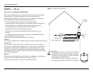
STEP 4 — OPERATE
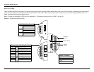
The Controller faceplate contains most functional elements of the user interface. Below is a description of that functionality.
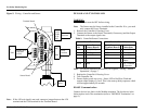
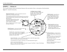
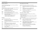
Figure 12: Controller Functionality
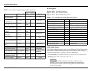
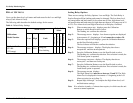
Status
Red
Slow Flash:
Gas present
Flast flash :
Cal or Fault
Solid:
Overrange
Pull
Here
Green
Short Blips:
Normal
operation.
No gas
present
C
a
l
/
R
e
s
e
t
M
a
g
n
e
t
O
n
S
i
d
e
Off
Power
On
Pull
Here
Current O/P Check
Connect current probes
to meter jacks and
read mA output
Calibration/Setup
-Hold Cal/Reset or
magnet until countdown
is zero (~10 sec)
-Follow instruction on
display
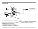
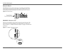
Magnetic Reed Switch - provides non-intrusive access for
programming, calibrating and resetting.
-Place magnet against Housing (where indicated) for less than one
second to initiate a basic system reset (clear a latched alarm) and
make selections.
-Place magnet against Housing (where
indicated) and hold to program, view
current settings and calibrate.
Refer to "Magnetic Reed Switch" on page 12
for further information.
Scrolling 8-character display -
provides various status messages and
prompts. Refer to "Status LEDs,
Display Messages and Current
Loop" on page 11.
Pull Here knob - unscrew the two
screws and gently pull to remove
faceplate. Removal allows access
to terminal boards. The faceplate
remains attached by the ribbon
cable.
Status Light (Red and Green) -
indicates status of unit. Refer to
"Status LEDs, Display Messages and
Current Loop" on page 11 for
detailed explanation of states/status.
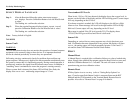
Current Test Jacks - to take current loop measurements use the following procedure:
-Insert your current meter leads into the Test Jacks.
-Set external devices to bypass, if necessary, to avoid unwanted alarm response
-Review current loop measurements.
Refer to "Current Loop Measurement (Test Jacks)" on page 12 and Table 2, "Status LEDs, Display
Messages and Current Loop", on page 11.
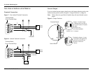
Calibration Button -providesintrusive
access for programming, calibrating and
resetting.
-Push for less than one second to initiate a
basic system reset (clear a latched gas
alarm) and make selections.
-Push and hold to program, view current
settings and calibrate.
Refer to "Calibration Button" on page 11
for further information.
ON/OFF Switch - used to turn Controller on and
off. Housing must be removed to access.
Pull Here knob - unscrew the two screws and
pull to remove faceplate. Removal allows
access to PCBs. The faceplate remains
attached by the ribbon cable.