


Net Safety Monitoring Inc
MLP-A/AR/AD-ST1400-25 6
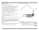
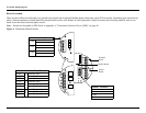
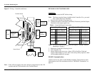
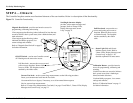
Figure 5: Wiring—Controller and Sensor
Note: If the 4-20 mA signal is not used, connect a jumper between the 4-20
terminal and the COM terminal on the Terminal Board.
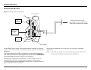
SENSOR AND CONTROLLER
WAR NI NG :
Power to the unit must be OFF before wiring.
Note: The Sensor may be factory installed to the Controller. If so, you need
only connect the Power Terminals.
1. Remove the Controller’s Housing Cover.
2. Connect the Sensor to the Sensor Terminals (if necessary) and the Output
Terminals to the output signal wires.
Note: For Sensor Separation instructions, see Figure 6, "Wiring—Sensor
Separation", on page 7.
3. Replace the Controller’s Housing Cover.
4. Turn Controller On.
5. Ensure display reads
Start Delay , Status LED is Red Slow Flash and
current output displays 3.0 mA. This is the start-up delay sequence which
will last approximately 90 seconds.
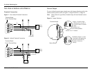
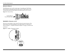
RS-485 Communication
Connect devices in a chain via the Modbus terminals. The last device in the
chain requires end of line termination (refer to "MODBUS Termination" on
page 9).
RST
+24V
COM
4-20
ISO
Red+
Blk
Shld
Red
Blk
-
-
Shld
Terminal Board
Sensor
Wires
Terminals
Modbus RTU
to PLC
A
B
COM
-
Terminals
Power
RST
+24V
COM
4-20
ISO
Terminals
Sensor
Sensor Board
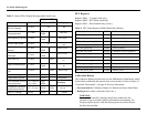
Table 1: Controller/Sensor Connections
Sensor Board Terminals Terminal Board Power
Sensor
Wire
Controller
(Sensor Board)
Controller
(Terminal Board)
Power
Connections
Red = Red (+24 V) RST = Remote Reset
Black = Blk (Sig) +24V = Power (+)
-COM=Power(-)
- 4-20 = Current Loop
Output
Shield = Shld ISO = +24 V isolated
4-20 power