


Installation & Operation Manual
64
Flue vent system and air piping
1. Visually inspect the entire flue gas venting system and air
piping for blockage, deterioration or leakage. Repair any
joints that show signs of leakage. Verify that air inlet pipe
is connected and properly sealed.
2. Verify that boiler vent discharge and air intake are clean
and free of obstructions.
Failure to inspect for the above conditions
and have them repaired can result in
severe personal injury or death.
Check water system
1. Verify all system components are correctly installed and
operational.
2. Check the cold fill pressure for the system. Verify it is
correct (must be a minimum of 12 psi).
3. Watch the system pressure as the boiler heats up (during
testing) to ensure pressure does not rise too high.
Excessive pressure rise indicates expansion tank sizing or
performance problem.
4. Inspect automatic air vents and air separators. Remove
air vent caps and briefly press push valve to flush vent.
Replace caps. Make sure vents do not leak. Replace any
leaking vents.
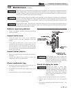
Check expansion tank
1. Expansion tanks provide space for water to move in and
out as the heating system water expands due to
temperature increase or contracts as the water cools.
Tanks may be open, closed or diaphragm or bladder type.
See Section 6 - Hydronic Piping for suggested best
location of expansion tanks and air eliminators.
Check boiler relief valve
1. Inspect the relief valve and lift the lever to verify flow.
Before operating any relief valve, ensure that it is piped
with its discharge in a safe area to avoid severe scald
potential. Read Section 6 - Hydronic Piping before
proceeding further.
Safety relief valves should be re-inspected AT
LEAST ONCE EVERY THREE YEARS, by a
licensed plumbing contractor or authorized
inspection agency, to ensure that the product
has not been affected by corrosive water
conditions and to ensure that the valve and
discharge line have not been altered or
tampered with illegally. Certain naturally
occurring conditions may corrode the valve
or its components over time, rendering the
valve inoperative. Such conditions are not
detectable unless the valve and its
components are physically removed and
inspected. This inspection must only be
conducted by a plumbing contractor or
authorized inspection agency – not by the
owner. Failure to re-inspect the boiler relief
valve as directed could result in unsafe
pressure buildup, which can result in severe
personal injury, death, or substantial
property damage.
Following installation, the valve lever must
be operated AT LEAST ONCE A YEAR to
ensure that waterways are clear. Certain
naturally occurring mineral deposits may
adhere to the valve, rendering it
inoperative. When manually operating
the lever, water will discharge and
precautions must be taken to avoid
contact with hot water and to avoid water
damage. Before operating lever, check to
see that a discharge line is connected to
this valve directing the flow of hot water
from the valve to a proper place of
disposal. Otherwise severe personal injury
may result. If no water flows, valve is
inoperative. Shut down the boiler until a
new relief valve has been installed.
2. After following the warning directions in this manual, if the
relief valve weeps or will not seat properly, replace the relief
valve. Ensure that the reason for relief valve weeping is the
valve and not over-pressurization of the system due to
expansion tank waterlogging or undersizing.
ƽ WARNING
ƽ WARNING
ƽ WARNING
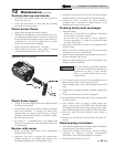
12 Maintenance
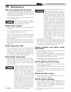
Inspect ignition and flame sense
electrodes
1. Remove the ignition and flame sense electrodes from the
boiler heat exchanger access cover.
2. Remove any deposits accumulated on the ignition/flame
sense electrode using sandpaper. If the electrodes cannot be
cleaned satisfactorily, replace with new ones.
3. Replace ignition/flame sense electrode, making sure gasket is
in good condition and correctly positioned.
Check ignition ground wiring
1. Inspect boiler ground wire from the heat exchanger access
cover to ground terminal strip.
2. Verify all wiring is in good condition and securely attached.
3. Check ground continuity of wiring using continuity meter.
4. Replace ground wires if ground continuity is not
satisfactory.
Check all boiler wiring
1. Inspect all boiler wiring, making sure wires are in good
condition and securely attached.
Check control settings
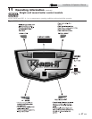
1. Set the SMART SYSTEM control module display to
Parameter Mode and check all settings. See Section 1 of the
Knight Wall Mount Service Manual. Adjust settings if
necessary. See Section 1 of the Knight Wall Mount Service
Manual for adjustment procedures.
2. Check settings of external limit controls (if any) and adjust
if necessary.