


Installation & Operation Manual
20
4 Sidewall direct venting (continued)
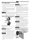
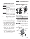
Sidewall termination – optional
concentric vent
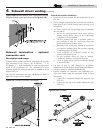
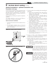
Description and usage
Lochinvar offers optional concentric combustion air and vent
pipe termination kits (Factory Kit #CVK3003 - 3" or
#CVK3008 - 2"). Both combustion air and vent pipes must
attach to the termination kit. The termination kit must
terminate outside the structure and must be installed as shown
below in FIG. 4-6.
The required combustion vent pipe and fittings are listed in
Table 3A, on page 14 of this manual.
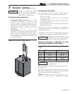
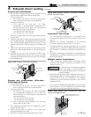
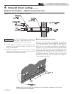
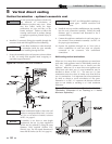
Figure 4-7 Kit Contents
Sidewall termination installation
1. Determine the best location for the termination kit (see
FIG. 4-6).
2. The total length of piping for vent or air must not exceed the
limits given in the General Venting Section on page 15 of
this manual.
3. You must consider the surroundings when terminating
the vent and air:
a. Position the vent termination where vapors will not
damage nearby shrubs, plants or air conditioning
equipment or be objectionable.
b. The flue products will form a noticeable plume as
they condense in cold air. Avoid areas where the
plume could obstruct window views.
c. Prevailing winds could cause freezing of condensate
and water/ice buildup where flue products impinge
on building surfaces or plants.
d. Avoid possibility of accidental contact of flue
products with people or pets.
f. Do not terminate above any door or window.
Condensate can freeze, causing ice formations.
g. Locate or guard vent to prevent condensate damage
to exterior finishes.
4. Cut one (1) hole (5 inch diameter for #CVK3003
installations or 4 inch diameter for #CVK3008 installations)
into the structure to install the termination kit.
5. Partially assemble the concentric vent termination kit.
Clean and cement using the procedures found in these
instructions.
a. Cement the Y concentric fitting to the larger kit pipe
(FIG. 4-7).
b. Cement the rain cap to the smaller diameter kit pipe
(FIG. 4-7).
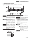
Figure 4-6 Concentric Sidewall Termination
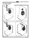
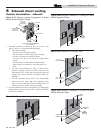
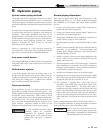
Figure 4-5B Alternate Multiple Vent Terminations w/Field
Supplied Fittings (must also comply with Figure 4-1B)