


Installation & Operation Manual
4 Sidewall direct venting (continued)
Termination and fittings
1. The air termination coupling must be oriented at least
12 inches above grade or snow line as shown in FIG. 4-1A,
page 17.
2. Maintain the required dimensions of the finished
termination piping as shown in FIG. 4-1A, page 17.
3. If using the alternate sidewall termination do not extend
exposed vent pipe outside of building more than shown in
this document. Condensate could freeze and block vent
pipe.
4. PVC/CPVC terminations are designed to accommodate any
wall thickness of standard constructions per the directions
found in this manual.
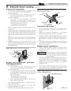
Prepare wall penetrations (Alternate -
Field Supplied Option)
1. Air pipe penetration:
a. Cut a hole for the air pipe. Size the air pipe hole as
close as desired to the air pipe outside diameter.
2. Vent pipe penetration:
a. Cut a hole for the vent pipe. For either combustible
or noncombustible construction, size the vent pipe
hole with at least a 1/2 inch clearance around the vent
pipe outer diameter:
• 3½ inch hole for 2 inch vent pipe
• 4½ inch hole for 3 inch vent pipe
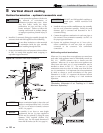
b. Insert a galvanized metal thimble in the vent pipe
hole as shown in FIG. 4-4B.
3. Use a sidewall termination plate as a template for correct
location of hole centers.
4. Follow all local codes for isolation of vent pipe when
passing through floors or walls.
5. Seal exterior openings thoroughly with exterior caulk.
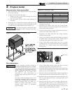
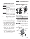
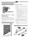
VENT PIPING
GALVANIZED
THIMBLE
VENT CAP
AIR PIPING
WALL PLATE
VENT PLATE
Figure 4-4A Sidewall Termination Assembly
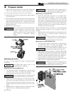
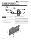
ELBOW
BIRD SCREEN
ELBOW
BIRD SCREEN
SIDEWALL
TERMINATION PLATE
GALVANIZED
THIMBLE
VENT PIPING
AIR PIPING
Figure 4-4B Alternate Sidewall Termination Assembly
w/Field Supplied Fittings
All vent pipes and air inlets must terminate
at the same height to avoid possibility of
severe personal injury, death, or substantial
property damage.
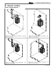
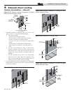
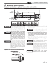
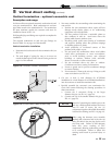
Multiple vent/air terminations
1. When terminating multiple Knight wall mount boilers
terminate each vent/air connection as described in this
manual (FIG. 4-5A).
2. Place wall penetrations to obtain minimum clearance of 12
inches between edge of air inlet and adjacent vent outlet, as
shown in FIG. 4-5A for U.S. installations. For Canadian
installations, provide clearances required by CSA B149.1
Installation Code.
3. The air inlet of a Knight wall mount boiler is part of a direct
vent connection. It is not classified as a forced air intake
with regard to spacing from adjacent boiler vents.
ƽ WARNING
12" MIN. BETWEEN EDGE OF AIR
INLET AND ADJACENT VENT OUTLET
VENT / AIR
TERMINATION
VENT
AIR
Figure 4-5A Multiple Vent Terminations (must also
comply with Figure 4-1A)
Prepare wall penetrations
1. Use the factory supplied wall plate as a template to locate
the vent and air intake holes and mounting holes.
Air pipe penetration:
a. Cut a hole for the air pipe. Size the air pipe hole as
close as desired to the air pipe outside diameter.
Vent pipe penetration:
a. Cut a hole for the vent pipe. For either
combustible or noncombustible construction, size
the vent pipe hole with at least a 1/2 inch clearance
around the vent pipe outer diameter:
• 3½ inch hole for 2 inch vent pipe
• 4½ inch hole for 3 inch vent pipe
Drill 3/16" diameter holes for inserting the plastic anchors
into the wall.
2. Install the vent and air intake piping through the wall into
the vent plate openings. Seal all gaps between the pipes and
wall. Use RTV silicone sealant to seal the air pipe. Use the
cement/primer listed in Table 3A on page 14 to seal the vent
pipe.
3. Mount and secure the vent plate to the wall using stainless
steel screws. Seal around the plate to the wall assuring no
air gaps.
4. Assemble the vent cap to the vent plate (see FIG. 4-4A).
Insert the stainless steel screws into the vent cap screw hole
openings and securely attach the vent cap to the vent plate.
5. Seal all wall cavities.
19