


Installation & Operation Manual
38
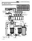
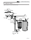
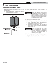
7 Gas connections
Nominal
Iron Pipe
Size (Inches)
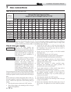
Natural Gas Pipe Capacity Chart
Length of Pipe in Straight Feet for 1/2 PSI
10
20
30
40
50
60
70
80
90
100
125
150
175
200
1/2
175 120 97 82 N/A N/A N/A N/A N/A N/A N/A N/A N/A N/A
3/4
369
256
205
174
155
141
128
121
113
106
95
86
79
74
1
697
477
384
328
292
267
246
236
210
200
179
164
149
138
1-1/4
1400
974
789
677
595
543
502
472
441
410
369
333
308
287
1-1/2
2150
1500
1210
1020
923
830
769
707
666
636
564
513
472
441
2
4100
2820
2260
1950
1720
1560
1440
1330
1250
1180
1100
974
871
820
2-1/2
6460
4460
3610
3100
2720
2460
2310
2100
2000
1900
1700
1540
1400
1300
3
11200
7900
6400
5400
4870
4410
4000
3800
3540
3330
3000
2720
2500
2340
4
23500
16100
13100
11100
10000
9000
8300
7690
7380
6870
6150
5640
5130
4720
Knight wall mount boilers are typically shipped ready to fire on natural gas. Check boiler rating plate to
determine which fuel the boiler is set for. If set to natural gas, it may be converted to LP by installing an
orifice (see page 11). In order to operate on LP gas, an orifice MUST BE installed. Failure to comply could
result in severe personal injury, death, or substantial property damage.
Table 7A Natural Gas Pipe Size Chart
The gas piping must be sized for the proper flow and length
of pipe, to avoid excessive pressure drop. Both the gas meter
and the gas regulator must be properly sized for the total gas
load.
If you experience a pressure drop greater than 1 inch w.c.,
the meter, regulator, or gas line is undersized or in need of
service. Perform the steps below when checking inlet gas
supply:
1. Turn the main power switch to the “OFF” position.
2. Shut off gas supply at the manual gas valve in the gas
piping to the appliance.
ƽ WARNING
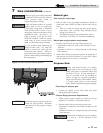
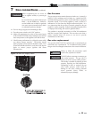
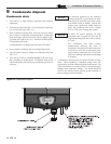
3. Loosen the set screw one (1) full turn from inside the
pressure tap on top of the gas valve. Place the tubing of
the manometer over the tap once the set screw is
loosened as shown in FIG. 7-3.
4. Slowly turn on the gas supply at the field installed
manual gas valve.
5. Turn the power switch to the “ON” position.
6. Adjust the temperature set point on the control panel of
the SMART SYSTEM control module to call for heat.
7. Observe the gas supply pressure as the burner fires at
100% of rated input. Percent of burner input will be
displayed on the control panel.
8. Ensure inlet pressure is within specified range.
Minimum and maximum gas supply pressures are
specified in this section of the manual.
9. If gas supply pressure is within normal range and no
adjustments are needed, proceed on to Step 11.
10. If the gas pressure is out of range, contact the gas utility,
gas supplier, qualified installer or service agency to
determine the necessary steps to provide proper gas
pressure to the control.
11. Turn the power switch to the “OFF” position.
12. Shut off the gas supply at the manual gas valve in the gas
piping to the appliance.
13. Remove the manometer from the pressure tap on top of
the gas valve. Re-tighten the set screw inside the pressure
tap.
Check inlet gas supply
NOTICE
CSA or UL listed flexible gas
connections are acceptable, but you
must exercise caution to ensure that the
line has adequate capacity to allow your
boiler to fire at full rate. Consult with
local codes for proper installation or
service procedures.
DO NOT adjust or attempt to measure
gas valve outlet pressure. The gas valve is
factory-set for the correct outlet
pressure. This setting is suitable for
natural gas and propane, requiring no
field adjustment. Attempting to alter or
measure the gas valve outlet pressure
could result in damage to the valve,
causing potential severe personal injury,
death, or substantial property damage.
ƽ WARNING