


Installation & Operation Manual
4
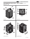
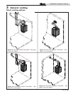
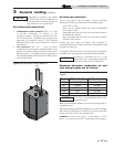
The Knight Wall Mount Boiler - How it works...
1. Stainless steel heat exchanger
Allows system water to flow through specially designed
coils for maximum heat transfer, while providing
protection against flue gas corrosion. The coils are
encased in a jacket that contains the combustion process.
2. Heat exchanger access cover
Allows access to the combustion side of the heat
exchanger coils.
3. Blower
The blower pulls in air and gas through the venturi (item
5). Air and gas mix inside the blower and are pushed into the
burner, where they burn inside the combustion chamber.
4. Gas valve
The gas valve senses the negative pressure created by the
blower, allowing gas to flow only if the gas valve is
powered and combustion air is flowing.
5. Venturi
The venturi controls air and gas flow into the burner.
6. Flue gas sensor
This sensor monitors the flue gas exit temperature. The control
module will modulate and shut down the boiler if flue gas
temperature gets too hot. This protects the flue pipe from
overheating.
7. Boiler outlet temperature sensor (housed with high
limit)
This sensor monitors boiler outlet water temperature (system
supply). If selected as the controlling sensor, the control
module adjusts boiler firing rate so the outlet temperature is
correct.
8. Boiler inlet temperature sensor
This sensor monitors return water temperature (system
return). If selected as the controlling sensor, the control
module adjusts the boiler firing rate so the inlet temperature is
correct.
9. Temperature and pressure gauge (field installed, not
shown)
Monitors the outlet temperature of the boiler as well as the
system water pressure.
10. Electronic display
The electronic display consists of 7 buttons and a dual line 32-
character liquid crystal display.
11. Flue pipe adapter
Allows for the connection of the PVC vent pipe system to the
boiler.
12. Burner (not shown)
Made with metal fiber and stainless steel construction,
the burner uses pre-mixed air and gas and provides a
wide range of firing rates.
13. Water outlet (system supply)
The water outlet is the water connection for water leaving the
boiler and entering the system. Boiler connection is 1".
14. Water inlet (system return)
The water inlet is the water connection for water entering the
boiler from the system. Boiler connection is 1".
15. Gas connection pipe
Threaded pipe connection of 1/2". This pipe should be
connected to the incoming gas supply for the purpose of
delivering gas to the boiler.
16. SMART Control Module
The SMART Control responds to internal and external signals
and controls the blower, gas valve, and pumps to meet the
heating demand.
17. Air intake adapter
Allows for the connection of the PVC air intake pipe to
the boiler.
18. High voltage junction box
The junction box contains the connection points for the line
voltage power and all pumps.
19. Automatic air vent
Designed to remove trapped air from the heat exchanger
coils.
20. Low voltage connection board
The connection board is used to connect external low voltage
devices.
21. Low voltage wiring connections (knockouts)
Conduit connection points for the low voltage
connection board.
22. Condensate drain connection
Connects the condensate drain line to a 1/2" pipe.
23. Access door
Provides access to all internal components.
24. Ignition electrode
Provides direct spark for igniting the burner.
25. Flame inspection window
The quartz glass window provides a view of the burner
surface and flame.
26. Gas shutoff switch
An electrical switch designed to cut power from the gas valve to
prevent releasing any gas.
27. High limit sensor (housed with outlet sensor)
Device that monitors the outlet water temperature. If the
temperature exceeds its setting, it will break the control circuit,
shutting the boiler down.
28. Relief valve
Protects the heat exchanger from an over pressure condition.
The relief valve may be set at 30 psi or 50 psi depending on
model.
29. Flame sensor
Used by the control module to detect the presence of burner
flame.
30. Line voltage wiring connections (knockouts)
Conduit connection points for the high voltage junction box.
31. Air pressure switch
The air pressure switch detects blocked inlet conditions.