


Installation & Operation Manual
2 Prepare boiler
11
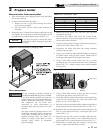
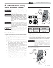
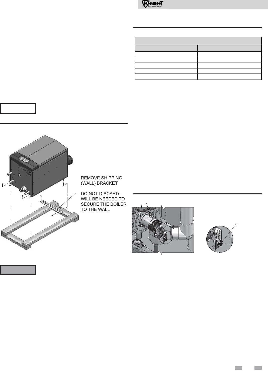
Remove boiler from wood pallet
1. After removing the outer shipping carton from the boiler,
remove the parts box.
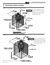
2. To remove the boiler from the pallet:
a. Remove the two (2) lag bolts securing the bottom
of the unit to the pallet.
b. Lift the boiler off the wall bracket mounted to
the pallet.
3. Remove the two (2) lag bolts securing the wall bracket to the
wood pallet. Be certain not to lose the wall bracket as it will
be needed for securing the boiler to the wall (FIG. 2-1).
Do not drop the boiler or bump the jacket
on the floor or pallet. Damage to the boiler
can result.
The gas conversion procedure should be
accomplished BEFORE the boiler is installed.
For a boiler already installed, you must turn
off gas supply, turn off power, and allow the
boiler to cool before proceeding. You must
also completely test the boiler after
conversion to verify performance as
described under Start-up, Section 10 of this
manual.
You must install the propane orifice to fire
the Knight wall mount boiler on propane.
Verify when installing that the orifice size
marking matches boiler size (Table 2A).
Failure to comply could result in severe
personal injury, death, or substantial
property damage.
1. Remove the front access cover from the unit (no tools
required for removal).
2. Disconnect the ribbon cable from the control board.
Remove the four (4) screws securing the bezel to the front of
the unit and remove the bezel.
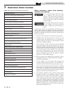
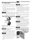
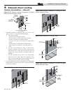
3. Locate the power switch on the gas valve and turn the power
switch to the “OFF” position (FIG. 2-2).
4. Disconnect the Molex plug from the wiring connector
located on the gas valve.
5. Using a 5/16" nut driver, loosen the band clamp securing the
air intake coupler to the gas valve venturi. Remove the air
intake pipe and coupler from the gas valve venturi.
6. Using a 4mm Allen wrench, remove the two (2) screws
securing the gas valve venturi to the inlet of the combustion
blower (FIG. 2-2). Remove the gas valve venturi assembly
from the unit.
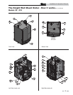
Figure 2-1 Boiler Mounted on Shipping Pallet
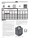
Gas conversions
LP Conversion Table
Model LP Orifice Stamping
50
50
80
80
105
105
150
210 / W150
210
210 / W150
NOTICE
ƽ WARNING
Table 2A LP Conversion Table
Figure 2-2 Gas Valve Power Switch & Venturi Removal
DETAIL
POWER SWITCH
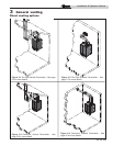
7. Using a 4mm Allen wrench, remove the four (4) screws
securing the gas valve to the venturi (FIG. 2-3).
8. Locate the propane orifice disk from the conversion kit bag.
Verify that the stamping on the orifice disk matches the
boiler size (50 - 210, see Table 2A).
9. Place the orifice into the black rubber grommet in the side of
the gas valve and secure inside the gas valve (see FIG. 2-3).
10. Reposition the gas valve against the venturi and replace the
four (4) screws removed in Step 7, securing the valve to the
venturi (FIG. 2-3).
11. Reposition the gas valve venturi assembly inside the unit.
Secure the gas valve venturi to the combustion blower by
replacing the two (2) screws removed in Step 6 (FIG. 2-2).
12. Reattach the air intake pipe and coupler to the gas valve
venturi. Tighten the band clamp to secure.