


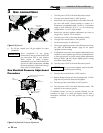

Low Water Cutoff (if equipped)
A hot water boiler installed above radiation level must be
provided with a low water cutoff device either as part of the
unit or installed at the time the boiler is installed. An
electronic low water cutoff is available as a kit on all units.
Low water cutoffs should be in spect ed every six months,
including flushing of float types.
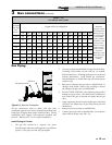
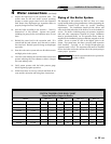
TABLE - 4A
MINIMUM REQUIRED FLOW
FOR HEATING BOILER
Input Btu/hr GPM Flow
45,000 1.9
75,000 3.1
90,000 3.7
135,000 5.6
180,000 7.4
215,000 8.9
260,000 10.7
NOTICE
Minimum flow is based on a 40°F
tem per a ture rise across the boiler.
Minimum flow may not prove a flow
switch installed in the boiler piping. Use
care when operating a boiler at or near
the min i mum recommended flow
because conditions unique to the
installation (system pressure, operation
of multiple zone valves, glycol,
variations in flow, etc.,) may result in
overheating of the boiler water caus ing
noise or nui sance operation of safety
limit con trols. Typical heat ing boiler
applications will op er ate with a 20°F to
30°F temperature rise across the boiler.
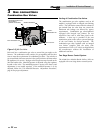
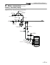
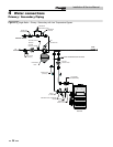
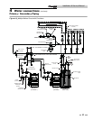
Typical Heating Boiler Installations
General Plumbing Rules
1. Check all local codes.
2. For serviceability of the boiler, always install unions.
3. Always pipe pressure relief valves to an open drain.
4. Locate system air vents at the highest point of the system.
5. Expansion tank must be installed near the boil er and on
the suction side of the pump.
6. Support all water piping.
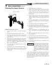
Placing the Boiler in Operation
Filling the System: All air must be purged from the system for
proper operation. An air scoop and air vent must be located
close to the boiler outlet and there should be a minimum
distance between the cold water feed and the system purge valve.
1. Close all drain cocks and air vents.
2. Open the makeup water valve and slowly fill the system.
3. If a makeup water pump is employed, ad just the pressure to
provide a minimum of 12 psi at the highest point in the
system. If a pressure regulator is also installed in the line,
it should be adjusted to the same pressure.
4. Close all valves. Purge one circuit at a time as follows:
A. Open one circuit drain valve and let the water drain for
at least five minutes. Ensure that there are no air
bubbles visible in the wa ter stream before closing the
drain valve.
B. Repeat this procedure for each circuit.
5. Open all valves after all circuits have been purged. Make
sure there are no system leaks.
NOTICE
Do not use petroleum based stop leak
products. All system leaks must be
repaired. The constant addition of
make-up water can cause damage to the
boiler heat exchanger due to scale
accumulation. Scale reduces flow and
heat transfer, causing overheating of the
heat exchanger.
6. Run the system circulating pump for a min i mum of 30
minutes with the boiler turned off.
7. Open all strainers in the system and check for debris.
8. Recheck all air vents as described in step 4, General
Plumbing Rules.
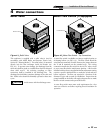
4 Water connections
24
Installation & Service Manual