


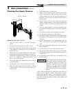

9. Inspect the liquid level in the expansion tank. The
system must be full and under normal operating
pressure to ensure proper water level in the expansion
tank. Ensure that diaphragm type ex pan sion tanks are
properly charged and not water logged.
10. Start the boiler according to the Section 6 - “Start-Up
Instructions” in this manual. Operate the system,
including the pump, boiler and radiation units, for one
hour.
11. Recheck the water level in the expansion tank. If it
exceeds half the tank volume, open the tank to reduce
the water level. Recheck pres sure charge on diaphragm
type tanks.
12. Shut down the entire system and vent all ra di a tion units
and high points in the system.
13. Close the water makeup valve and check the strainer and
pressure reducing valve for sediment or debris. Reopen
the water makeup valve.
14. Verify system pressure with the boiler pres sure gauge
before beginning regular operation.
15. Within three days of start-up, recheck and bleed all air
vents and the expansion tank using these instructions.
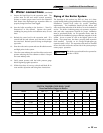
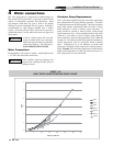
TABLE - 4B
SYSTEM TEMPERATURE RISE CHART
Based on Boiler Output in Btu/hr
Btu/hr
10°F T 20°F T 30°F T 40°F T
Input Output GPM Ft/hd GPM Ft/hd GPM Ft/hd GPM Ft/hd
45,000 36,900 7.4 0.6 3.7 0.2 2.5 0.2 1.9 0.2
75,000 61,500 12.3 1.3 6.2 0.4 4.1 0.3 3.1 0.2
90,000 73,800 14.9 1.4 7.4 0.5 5.0 0.3 3.7 0.2
135,000 110,700 22.3 3.2 11.1 1.2 7.4 0.6 5.6 0.3
180,000 147,600 29.7 5.1 14.9 1.6 9.9 0.7 7.4 0.4
215,000 176,300 -- -- 17.0 1.3 11.8 0.8 8.9 0.4
260,000 213,200 -- -- 21.5 2.1 14.3 0.9 10.7 0.5
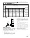
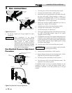
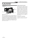
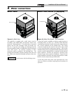
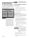
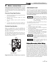
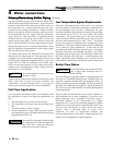
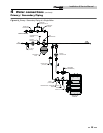
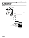
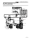
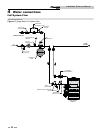
Piping of the Boiler System
The drawings in this section (see FIG’s 4-7 thru 4-11) show
typical heating boil er piping installations. Before beginning the
in stal la tion, consult local codes for specific plumb ing
re quire ments. The installation should provide unions and
valves at the inlet and outlet of the boil er so it can be isolated for
service. The boiler cir cu lat ing pump, air sep a ra tor, expansion
tank and oth er components required for proper installation
must be purchased locally. An air separation device must be
supplied in the in stal la tion piping to eliminate trapped air in the
system. Lo cate a system air vent at the highest point in the
sys tem. The system must also have a properly sized expansion
tank installed. Typically, an air charged di a phragm-type
expansion tank is used. The expansion tank must be installed
close to the boiler and on the suction side of the system pump to
ensure proper op er a tion.
ƽ CAUTION
This boiler system should not be operated at
less than 12 PSIG.
4 Water connections (continued)
25
Installation & Service Manual