


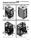
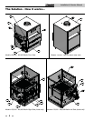
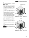

The Solution - How it works...
1. Control panel cover
The control panel cover provides access to the thermostat, ignition
module, and transformer.
2. Burner (not shown)
The burner is a cylindrical stainless steel tube used to regulate
burner flame.
3. Drain port
Location from which the heat exchanger can be drained.
4. Flue outlet
The flue outlet allows the connection of the vent pipe to the unit.
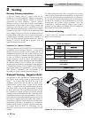
5. Gas connection
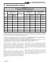
The gas pipe connection on this appliance is 1/2", or 3/4" NPT. To
deliver the correct amount of gas volume to the appliance it may
be necessary to have a larger gas line reduced at the appliance.
Please reference the National Fuel Gas Code charts for more
details.
6. Gas valve
The gas valve allows the proper amount of gas to pass into the
burner for combustion.
7. Heat exchanger
The heat exchanger allows system water to flow through specially
designed tubes for maximum heat transfer. The glass lined
headers and copper finned tubing are encased in a jacket that
contains the combustion process.
8. High limit sensor
Device that monitors the outlet water temperature to ensure
safe operation. If the temperature exceeds its setting, it will break
the control circuit, shutting the appliance down.
9. Ignition module
The ignition module responds to a call for heat signal to provide
burner operation.
10. Junction box
The junction box contains the connection points for the line
voltage power and all pumps.
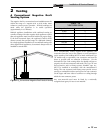
11. Performance loop
A pumped bypass provides constant flow through the heat
exchanger when the building system flow is reduced.
12. Performance Loop Pump
The pump ensures adequate flow to operate the unit.
13. Pilot (not shown)
The pilot is a spark ignition device used to light a pilot flame which
in turn is used to light the main burners.
14. Pump relay
The pump relay energizes the pump on a call for heat.
15. Relief valve
The relief valve is a safety device that ensures the maximum
pressure of the appliance is not exceeded.
16. Sight Glass
The sight glass provides a view of the burner surface, burner flame,
and the pilot flame.
17. Temperature and pressure gauge
The temperature and pressure gauge monitors the outlet
temperature of the appliance as well as the system water
pressure.
18. Temperature sensor
This sensor monitors inlet water temperature. If selected as the
controlling sensor, the appliance will maintain the setpoint at this
sensor.
19. Terminal strip
The boiler is equipped with a terminal strip on the left side of the
unit to allow easy connection to contact points.
20. Top panel
Removable panel to gain access to the internal components.
21. Thermostat
The thermostat monitors the water temperature via a temperature
sensor and will initiate a call for heat when the water temperature
drops below the setpoint plus the differential on the thermostat.
22. Transformer
The transformer reduces 120 VAC supply voltage to 24 VAC for the
control circuit.
23. Water inlet (system return)
The water inlet is a 1 1/2" pipe connection that receives water
from the system and delivers it to the heat exchanger.
24. Water outlet (system supply)
The water outlet is a 1 1/2" pipe connection that supplies
water to the system with connections for a flow switch, a relief
valve, and a temperature and pressure gauge.
25. Gas manifold pipe
Delivers gas from the gas valve to the main burners through a
number of orifices.
Installation & Service Manual
6