


5 Electrical connections (continued)
37
Installation & Service Manual
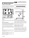
Outdoor Air Temperature Sensor
The outside air temperature sensor will only be used for
boiler systems. The outside air sensor is optional. This sensor
allows you to tie boiler operation to the outdoor air
temperature. As outside temperatures drop, the control will
increase the temperature setting of the boiler. As outdoor
temperatures rise, the control will decrease the temperature
to the selected set point of the boiler. You can set the control
to shut the boiler off when a desired outdoor air temperature
level is reached.
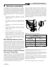
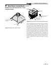
You must purchase the sensor from the appliance
manufacturer. The sensor comes with a housing that helps
protect the sensor from the elements. Mount the air sensor
housing outdoors, under the eve of the roof. Make sure the
housing is out of direct sunlight. This will ensure that the
sensor will accurately read the true outdoor temperature.
Connect the outdoor air temperature sensor to the terminal
block on the outdoor air reset board. For more information
on wiring the sensor, see Wiring of Remote Sensors, this page.
Wiring of Remote Sensors
To wire remote sensors, follow the guidelines below. Take care
to correctly wire sensors to the unit. Erratic temperature
readings can be caused by poor wiring practices. Twist the
wires between the unit and the remote sensor. Turn wires at
least three or four turns per linear foot of wiring. This
provides protection against some types of electrical
interferences.
1. Do not route temperature sensor wiring with building
power wiring.
2. Do not locate temperature sensor wiring next to control
contactors.
3. Do not locate temperature sensor wiring near electric
motors.
4. Do not locate temperature sensor wiring near welding
equipment.
5. Make sure good mechanical connections are made to the
sensor, any interconnecting wiring and the controller.
6. Do not mount sensor with leadwire end pointing up in an
area where condensation can occur.
7. Use shielded wiring to connect the sensor to the control
when the possibility of an electrically noisy environment
exists. Shielded cable is recommended on all cable runs of
more than 25 feet in length.
NOTICE
Ground the cable shield at the connection
to the boiler temperature control only. Do
not ground the shielded cable at the sensor
end.
To maintain temperature accuracy, sensor
wires should be 18 AWG two conductor
(18/2). Use shielded wire if required.
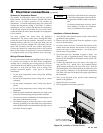
Installation of Remote Sensors
1. Turn OFF the main electrical power and the main manual
gas shutoff to the appliance.
2. Remove the side access panel from the appliance to gain
access to the thermostat.
3. Locate the sensor in the kit. Determine the location of the
remote sensor and measure the amount of wire needed to
connect the sensor to the thermostat. See Wiring of the
Remote Sensors for guidelines.
4. Use twisted pair wire, minimum 18 gauge or larger. See
Table 5A, page 34 regarding distance versus wire gauge.
Ensure all wire insulation is trimmed to reveal at least 3/8"
of exposed wire.
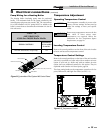
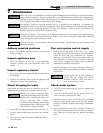
5. Connect the measured wire to the sensor wire using wire
caps (see FIG. 5-4). Install .250 x .032 insulated female
quick connect terminals to the end of the wires. Feed the
wires through the access hole located on the back of the unit
and secure the connectors to the thermostat connections
(Sys/Tank) CN5 and CN6 located in the upper right-hand of
the thermostat.
6. Turn on the electrical power and the main manual gas
shutoff to the appliance.
7. Replace the side access panel.
8. Fire the appliance and resume operation.
ACCESS HOLE
CONNECT THE MEASURED
WIRE TO THE SENSOR WIRE
Figure 5-4_Installation of Remote Sensors