


34
Installation & Service Manual
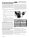
5 Electrical connections
This appliance is wired for 120 VAC service. The appliance,
when installed, must be electrically ground ed in accordance
with the requirements of the authority having jurisdiction or
in the absence of such re quire ments, with the latest edition of
the National Electrical Code ANSI/NFPA No. 70. When the
unit is in stalled in Canada, it must conform to the CSA C22.1,
Ca na di an Electrical Code, Part 1 and/or local Electrical
Codes.
1. All wiring between the appliance and field
in stalled devices shall be made with type T wire
[63° F(35° C) rise].
2. Line voltage wire exterior to the appliance must be
enclosed in approved conduit or approved metal clad
cable.
3. The pump must run continuously when the appliance is
being fired.
4. To avoid serious damage, DO NOT en er gize the
appliance until the system is full of water. Serious
damage may result.
5. Provide the unit with proper overload protection.
6. Install a wall thermostat on the inside wall. DO NOT
install the thermostat in an area affected by drafts,
sunlight, light fixtures, hot or cold water pipes or near a
fireplace. See “Room Thermostat or Remote Thermostat
Connection to Terminal Strip” (this page), for prop er
wiring con nec tion.
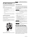
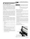
Boiler Operating Temperature Control
The operating temperature control is located in the control
panel, behind the control panel front ac cess door. The sensing
element for the operator is placed in a bulbwell installed in
the heat exchanger. Carefully observe the inlet water
temperature on the initial boiler on cycles. The exact
temperature set point is based on your system’s requirements.
Turn the con trol set point dial to the desired operating water
tem per a ture. Observe the boiler discharge tem per a ture after
each set point adjustment to ensure prop er operation.
Room Thermostat or Remote Thermostat
Connection to Terminal Strip
A room thermostat or remote temperature control may be
connected to the boiler. The room ther mo stat should be
installed on an inside wall, away from the influences of drafts,
hot or cold water pipes, lighting fixtures, televisions, sun rays
or fire plac es. Follow the manufacturers instructions supplied
with the ther mo stat for proper installation and ad just ment.
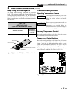
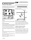
The boiler is equipped with a terminal strip on the left side of
the control panel to allow easy connection (FIG. 5-1).
Remove the jumper between the R and W terminals on the
terminal strip. Refer to the chart in this section (Table 5A) to
determine maximum allowable length and wire gauge
recommended to connect the switching con tacts of the room
thermostat to the R and W terminals on the terminal strip.
Connection to the terminal strip will allow the room thermostat
to make and break the 24VAC boiler control circuit turning the
boiler on and off based on the room ambient temperature
re quire ments. Set the boiler operating temperature control as
described in this section.
A
B
Figure 5-1_Terminal Strip Connections
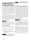
Auxiliary Device Connection to Terminal
Strip
A terminal connection strip is provided for ease of connection
for Power Venting Systems, see FIG. 5-1, inset A.
A field supplied powered venter or powered louver/damper may
be connected to the Solution boiler via a terminal strip located
on the left side of the unit, see FIG. 5-1, inset B.
A 24 VAC relay can be powered from this location when a call for
heat has been established. A device proving switch can be
interlocked back to the appliance to ensure its operation before
the appliance is allowed to fire.
Reference the wiring diagram on page 50 of this manual.
TABLE - 5A
TERMINAL STRIP WIRING
Wire Gauge
Allowable Length
Maximum
12 GA 100 ft.
14 GA 75 ft.
16 GA 50 ft.
18 GA 30 ft.