


53
General
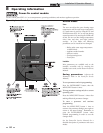
How the appliance operates
The Power-fin uses a copper finned tube heat exchanger to
transfer heat from the flue products to the water. An electronic
control module monitors various inputs to initiate a call for
heat. The blower provides both primary and secondary air to
the burner and forces the flue products out of the combustion
chamber and into the vent system. The control module
regulates the blower speed to control the firing rate of the unit.
The modulating gas valve monitors the amount of combustion
air being pulled into the blower and regulates the amount of gas
supplied, which then mixes with the combustion air and is
supplied to the burner.
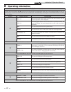
0 - 10V input (set point or power)
The Power-fin can be controlled by a Building Management
System (BMS) using a 0 - 10 VDC signal. The control can be
configured by the installer to use this signal to either control set
point or firing rate.
DHW priority (boiler only)
The SMART SYSTEM control module allows connection of a
DHW thermostat or tank sensor to the low voltage connection
board. When the DHW thermostat or tank sensor calls for heat,
the module activates the DHW pump, shuts down the boiler
pump, and immediately sets the target outlet water temperature
to 180°F (82.2°C). This provides automatic priority heat
allocation to the indirect water heater for maximum response
and recovery. The DHW pump continues for 30 seconds after
the heating cycle to deliver the most possible heat.
DHW / SH (space heating) cycling (boiler only)
If an indirect DHW call for heat is received while a space heating
call is in progress, the control will start the DHW pump and shut
the boiler pump off. The system pump will remain on. If the
space heating call is still active while the DHW call is in
operation, the control will wait for 30 minutes (time adjustable
by installer) then it will switch back to the space heating
demand. The control will switch back and forth until one of the
heat demands end.
Programmable controlling sensor (boiler only)
The control module is programmed to use the outlet sensor as
the control sensor by default. If a system supply sensor is
connected, the control automatically uses it as the control sensor.
The control sensor can be changed by the installer to the inlet
sensor. In this case, if a system return sensor is installed, the
control automatically uses it as the control sensor. If the inlet
sensor is chosen as the controlling sensor, it is recommended
that the system supply sensor be installed for the best system
performance.
Anti-cycling (boiler only)
After the set point has been satisfied, the control will delay the
next burner cycle for a set time period (time is adjustable by the
installer). The time delay will be bypassed if the system return
temperature drops too far during the delay.
Boiler, system, and DHW pump control
When a space heating call for heat starts and no DHW call is on,
the system and boiler pumps are turned on. As long as the space
heating call for heat is on, the system pump will remain on. If a
DHW call for heat is on, the boiler pump will wait to turn on
until just before the DHW pump turns off. After the space
heating call for heat ends, both pumps will run for an additional
period of time.
When a DHW call for heat starts, the DHW pump is turned on.
If a space heating call for heat was on, the boiler pump will turn
off a few seconds after the DHW pump turns on.
NOTICE
If an inline high gas pressure regulator is
used, it MUST BE of the lockup type and be
located a minimum of 10 feet from the
appliance. Failure to do so may result in
insufficient gas volume supplied to the
appliance.
NOTICE
If a pressure drop of more than 2" water
column occurs between Standby (static)
Mode and Operating (dynamic) Mode, a gas
volume problem exists. Contact the gas
utility, gas supplier, qualified installer, or
service agency to determine the necessary
steps to provide the proper gas volume to the
appliance.
How the control module operates
The SMART SYSTEM control module receives input from
appliance sensors and external devices. The control module
activates and controls the blower and gas valve to regulate heat
input and switches the boiler, Domestic Hot Water (DHW), and
system pumps on and off as needed. The user programs the
module to meet system needs by adjusting control parameters.
These parameters set operating temperatures and appliance
operating modes. Boiler operation can be based on boiler outlet
water temperature, boiler inlet water temperature, system
supply temperature, or system return temperature, depending
on the parameter setting. Water heater operation can be based
on a tank sensor or a tank thermostat.
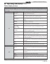
Control inputs and outputs
Enable
This input tells the boiler to provide water for space heating.
Tank thermostat
This input tells the boiler to provide water for heating a
domestic hot water tank.
8 Operating information (continued)
Installation & Operation Manual