


Installation & Operation Manual
12
1 Determine unit location
The result is improper combustion and a non-warrantable,
premature appliance failure.
EXHAUST FANS: Any fan or equipment which exhausts air
from the equipment room may deplete the combustion air
supply and/or cause a downdraft in the venting system. Spillage
of flue products from the venting system into an occupied living
space can cause a very hazardous condition that must be
immediately corrected. If a fan is used to supply combustion air
to the equipment room, the installer must make sure that it does
not cause drafts which could lead to nuisance operational
problems with the appliance.
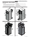
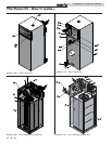
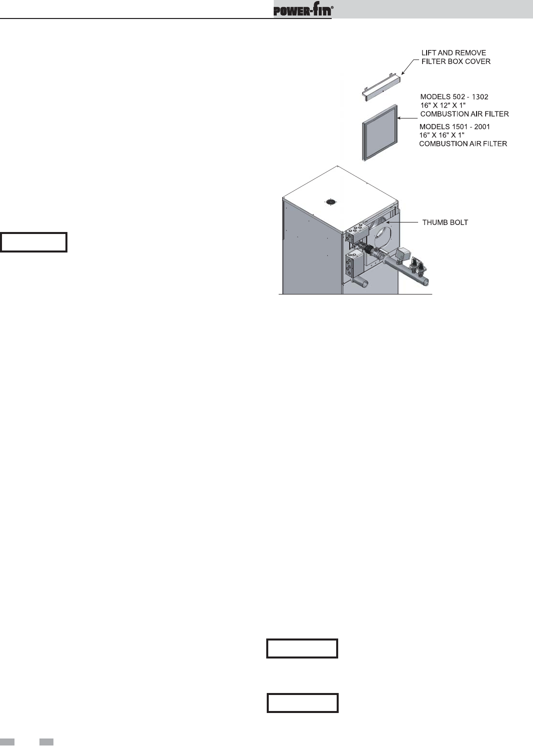
Figure 1-6_Filter Access
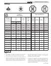
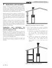
Combustion air requirements are based on the latest edition of
the National Fuel Gas Code, ANSI Z223.1; in Canada refer to
the latest edition of CGA Standard CAN B149.1 or B149.2.
Check all local code requirements for combustion air.
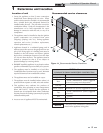
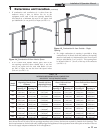
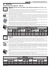
All dimensions based on net free area in square inches. Metal
louvers or screens reduce the free area of a combustion air
opening a minimum of approximately 25%. Check with louver
manufacturers for exact net free area of louvers. Where two
openings are provided, one must be within 12" (30cm) of the
ceiling and one must be within 12" (30cm) of the floor of the
equipment room. Each opening must have net free area as
specified in the chart on page 11 (Table 1B). Single openings
shall commence within 12" (30cm) of the ceiling.
ƽ CAUTION
Under no circumstances should the
equipment room ever be under negative
pressure. Particular care should be taken
where exhaust fans, attic fans, clothes dryers,
compressors, air handling units, etc., may
take away air from the unit.
The combustion air supply must be
completely free of any flammable vapors that
may ignite or chemical fumes which may be
corrosive to the appliance. Common
corrosive chemical fumes which must be
avoided are fluorocarbons and other
halogenated compounds, most commonly
present as refrigerants or solvents, such as
Freon, trichlorethylene, perchlorethylene,
chlorine, etc. These chemicals, when burned,
form acids which quickly attack the heat
exchanger finned tubes, headers, flue
collectors, and the vent system.
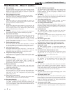
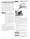
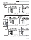
Combustion air filter
This unit has a standard air filter located at the combustion air
inlet as shown above in FIG. 1-6. This air filter is provided to
help ensure clean air is used for the combustion process. Check
this filter every month and replace when it becomes dirty. The
filter size on Models 502 -1302 is 16" x 12" x 1" (40.6cm x 30.5cm
x 2.5cm) and for Models 1501 - 2001 it’s 16" x 16" x 1" (40.6cm
x 40.6cm x 2.5cm). You can find these commercially available
filters at any home center or HVAC supply store. Follow the
steps below when replacing the combustion air filter:
1. Locate the combustion air filter box mounted on the rear of
the appliance.
2. Locate the flat thumb bolt at the top of the air filter box and
turn it a 1/4 turn counterclockwise to align it with the slot
in the air filter box.
3. Lift and remove the air filter box cover to gain access to the
air filter.
4. Slide the air filter out the top of the air filter box.
5. Inspect the air filter for dirt and debris, replace if necessary.
6. Replace the air filter and the air filter box cover. Turn the
thumb bolt clockwise a 1/4 turn to secure the air filter box
cover to the air filter box.
CAUTION
During construction the air filter should be
checked more frequently to ensure it does not
become clogged with combustion dirt and
debris.
NOTICE
Sustained operation of an appliance with a
clogged burner may result in nuisance
operational problems, bad combustion, and
non-warrantable component failures.