


71
Location of Cold Water Supply Piping Connections
Incorrect piping of the cold water supply to the system may
result in excessive low temperature operation causing
condensate formation on the primary heat exchanger and
operational problems. The cold water supply piping must be
installed in the discharge piping from the heater to the storage
tank. This allows the cold water to be tempered in the storage
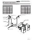
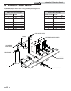
tank before entering the heater. See typical installation drawings
provided in this manual for correct piping (FIG.’s 9-1 thru 9-4).
Higher water temperatures reduce the volume of condensate
formed.
ƽ CAUTION
Setting the temperature selector to higher
settings provides hotter water, which
increases the risk of scald injury.
ƽ WARNING
Should overheating occur or the gas supply
fail to shut off, do not turn off or disconnect
the electrical supply to the pump. Instead,
shut off the gas supply at a location external
to the appliance.
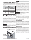
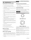
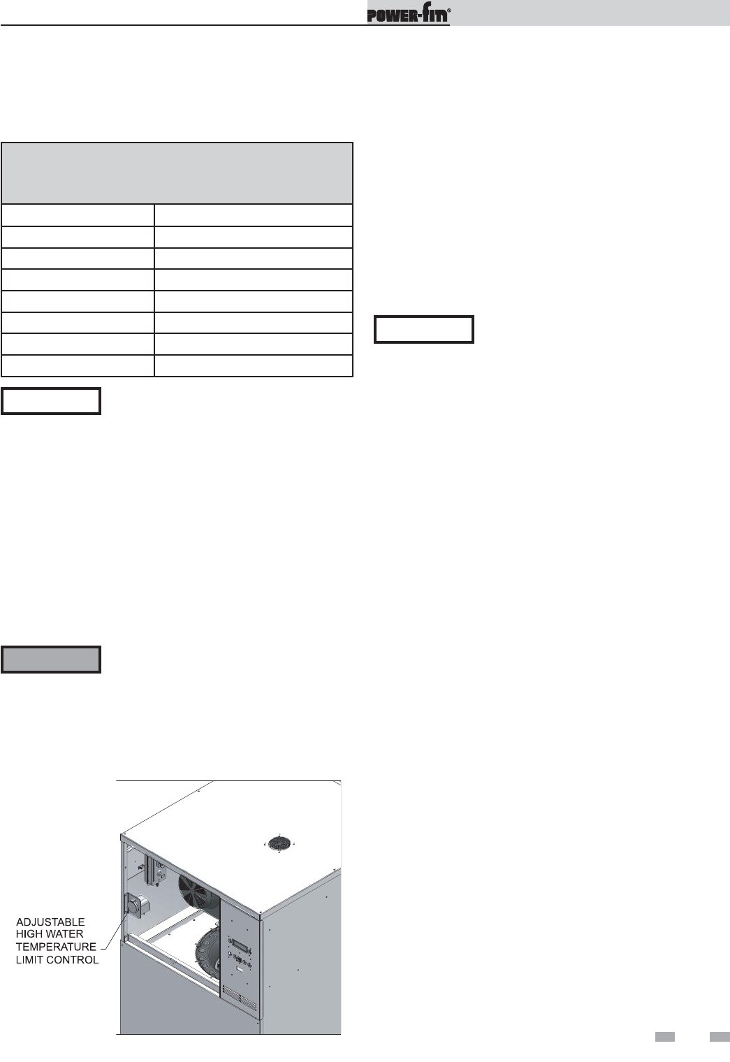
Adjustable high water temperature limit
control
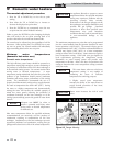
Figure 9-6_Adjustable High Water Temperature Limit Control
A high limit control is located on the inside of the left front
panel, as shown in FIG. 9-6. The setting of this control knob
limits maximum discharge water temperature. The water heater
temperature limit control is adjustable up to a maximum setting
of 210°F (99°C). This water heater also includes a fixed high
water temperature limit control set to 200° (93.3°C). The
RESET key on the display must be pushed whenever water
temperature has exceeded the set point of the limit. The
temperature of the water in the heat exchanger must drop a
minimum of 15°F (8.3°C) below the setting of the high limit
control before the reset function can be activated. A high limit
message will be shown in the Operator Interface when water
temperature exceeds the high water temperature limit control
set point.
Optional relief valve
This water heater is normally supplied with a temperature and
pressure relief valve sized in accordance with applicable codes.
Units may be supplied with an optional pressure only relief
valve. When a water heater is equipped with this optional relief
valve and is piped to a separate storage vessel, the storage vessel
must have a properly installed temperature and pressure relief
valve which complies with local codes.
Thermal expansion
A relief valve that discharges periodically may be due to thermal
expansion in a closed system. A water heater installed in a closed
system, such as one with a backflow preventer or check valve
installed in the cold water supply, shall be provided with means
to control expansion. Contact the water supplier or local
plumbing inspector on how to correct this situation. Do not
plug or cap the relief valve discharge.
Cathodic protection
Hydrogen gas can be produced in a hot water system that has not
been used for a long period of time (generally two weeks or
more). Hydrogen gas is extremely flammable. To prevent the
possibility of injury under these conditions, we recommend the
hot water faucet be open for several minutes at the kitchen sink
before you use any electrical appliance which is connected to the
hot water system. If hydrogen is present, there will be an
unusual sound such as air escaping through the pipe as the hot
water begins to flow. There should be no smoking or open
flames near the faucet at the time it is open.
NOTICE
The high limit control will not reset until the
water temperature has dropped below the set
point of the high limit.
9 Domestic water heaters (continued)
Installation & Operation Manual
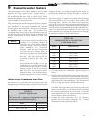
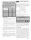
The following chart (Table 9E) details the relationship of water
temperature and time with regard to scald injury and may be
used as a guide in determining the safest water temperature for
your applications.
TABLE 9E
APPROXIMATE TIME / TEMPERATURE
RELATIONSHIPS IN SCALDS
120°F More than 5 minutes
125°F 1 1/2 to 2 minutes
130°F About 30 seconds
135°F About 10 seconds
140°F Less than 5 seconds
145°F Less than 3 seconds
150°F About 1 1/2 seconds
155°F About 1 second