


42
Installation & Operation Manual
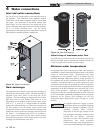
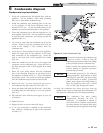
The installer must ensure that the boiler is supplied with
adequate flow without excessive temperature rise. It is
recommended that this boiler be installed with a bypass in the
piping if the maximum recommended flow rate is exceeded.
The bypass will help to ensure that the boiler can be supplied
with adequate water flow. Flow rates exceeding the maximum
recommended flow will result in erosion of the boiler tubes. A
typical bypass with a valve as shown in FIG. 4-5 will allow
control of boiler flow.
TABLE - 4C
BOILER TEMPERATURE RISE AT MAXIMUM FLOW
Temperature Rise at Full Rate Fire, 75 and 90 GPM
Maximum Flow
Model Temperature Rise
502 11°F (6.1°C)
752 17°F (9.4°C)
1002 23°F (12.8°C)
1302 30°F (16.7°C)
1501 28°F (15.6°C)
1701 32°F (17.8°C)
2001 38°F (21.1°C)
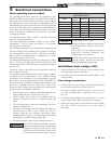
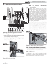
Boiler bypass requirements
TABLE - 4B
SYSTEM TEMPERATURE RISE CHART
Temperature Rise and Head Loss Based on Boiler Output in Btu/hr
Btu/hr 30°F ΔT 35°F ΔT 40°F ΔT 45°F ΔT 50°F ΔT 55°F ΔT 60°F ΔT
Input Output GPM Ft/hd GPM Ft/hd GPM Ft/hd GPM Ft/hd GPM Ft/hd GPM Ft/hd GPM Ft/hd
500,000 435,000 29.0 0.9 24.9 0.7 21.8 0.5 19.3 0.4 17.4 0.3 15.8 0.2 14.5 0.1
750,000 652,500 43.5 2.1 37.3 1.8 32.6 1.3 29.0 1.0 26.1 0.8 23.7 0.7 21.8 0.6
1,000,000 870,000 58.0 4.8 49.7 3.3 43.5 2.4 38.7 2.0 34.8 1.6 31.6 1.2 29.0 1.1
1,300,000 1,131,000 75.4 9.8 64.7 6.9 56.6 4.6 50.3 3.6 45.3 2.9 41.1 2.2 37.7 1.9
1,500,000 1,275,000 87.9 9.8 75.3 7.7 65.9 6.3 58.6 5.2 52.9 4.2 47.9 3.3 43.9 2.7
1,700,000 1,445,000 99.6* 14.1 85.4 10.2 74.7 7.9 66.4 6.5 59.8 5.3 54.3 4.6 49.8 3.9
2,000,000 1,700,000 117.2* 20.2 100.4* 14.9 87.9 11.9 78.1 9.2 70.3 7.2 63.9 6.4 58.6 5.2
*Cupro-Nickel Heat Exchanger Required at Flows Above 75 GPM on Models 502 - 1302 and above 90 GPM on Models 1501 - 2001.
Temperature / pressure gauge
This boiler is equipped with a dial type temperature / pressure
gauge. This gauge is factory installed in the outlet side of the
boiler piping. The gauge has one scale to read system pressure
and a separate scale to read water temperature in degrees
Fahrenheit. The temperature / pressure gauge is provided to
meet code requirements. Water temperatures can be more
accurately monitored from the data provided in the digital
display in the Operator Interface.
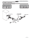
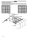
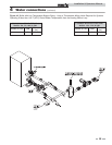
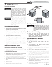
Typical heating boiler installations
General plumbing rules:
1. Check all local codes.
2. For serviceability of boiler, always install unions.
3. Always pipe pressure relief valve to an open drain.
4. Locate system air vents at highest point of system.
5. Expansion tank must be installed near the boiler and
on the suction side of the system pump.
6. Support all water piping.
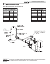
Installation with a chilled water system
Pipe refrigeration systems in parallel. Install duct coil
downstream at cooling coil. Where the hot water heating boiler
is connected to a heating coil located in the air handling units
which may be exposed to refrigeration air circulation, the boiler
piping system must be equipped with flow control valves or
other automatic means to prevent gravity circulation of the
boiler water during the cooling cycle.
The coil must be vented at the high point and hot water from
the boiler must enter the coil at this point. Due to the fast
heating capacity of the boiler, it is not necessary to provide a
ductstat to delay circulator operation. Also, omit thermostat
flow checks as the boiler is cold when heating thermostat is
satisfied. This provides greater economy over maintaining
standby heat.
4 Water connections