


Installation & Operation Manual
10
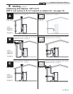
1 Determine unit location
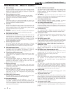
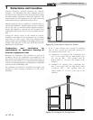
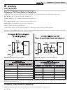
Figure 1-2_Combustion Air Direct from Outside
Combustion and ventilation air
requirements for appliances drawing air
from the equipment room
Provisions for combustion and ventilation air must be in
accordance with Air for Combustion and Ventilation, of the
latest edition of the National Fuel Gas Code, ANSI Z223.1, in
Canada, the latest edition of CGA Standard B149 Installation
Code for Gas Burning Appliances and Equipment, or applicable
provisions of the local building codes.
The equipment room MUST be provided with properly sized
openings to assure adequate combustion air and proper
ventilation.
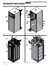
Maintain minimum specified clearances for adequate
operation. All installations must allow sufficient space for
servicing the vent connections, water pipe connections, piping
and other auxiliary equipment, as well as the appliance. The
clearance labels on each appliance note the same service and
combustible clearance requirements as shown above.
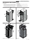
Multiple appliances may be installed in a modular boiler or
water heater installation. Multiple appliances may be installed
side by side with no clearance between adjacent appliances
because this appliance is approved for zero clearance from
combustible surfaces and no service access is required from the
sides.
Consult the Venting section of this manual for specific
installation instructions for the appropriate type of venting
system that you will be using. Direct Vent and DirectAire
venting systems require installation with Category IV flue pipe,
sealed air inlet pipe, and air inlet caps, which must meet the
manufacturer’s specifications.
1. If air is taken directly from outside the building
with no duct, provide two permanent openings to
the equipment room (see FIG. 1-2):
(a) Combustion air opening, with a minimum free
area of one square inch per 4000 Btu/hr input
(5.5 cm
2
per kW). This opening must be
located within 12" (30 cm) of the bottom of the
enclosure.
(b) Ventilation air opening, with a minimum free
area of one square inch per 4000 Btu/hr input
(5.5 cm
2
per kW). This opening must be
located within 12" (30 cm) of the top of the
enclosure.
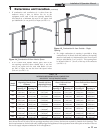
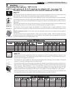
Figure 1-3_Combustion Air Through Ducts