


3
2 Configuration
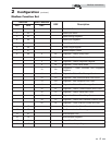
Addressing
The Modbus addressing space is comprised of 256 different
addresss.
• 0 is reserved for broadcast messages from the master
device
• 1 - 247 are free to use for each unique device
• 248 - 255 are reserved
To set the Modbus address the dip switches can be set in
either the 0 position or the 1 position. For switches set to the
1 position their value will be added together to determine the
address.
For each switch set to the 1 position it has the following value:
Dip switch 1 = 1
Dip switch 2 = 2
Dip switch 3 = 4
Dip switch 4 = 8
Dip switch 5 = 16
Dip switch 6 = 32
Dip switch 7 = 64
Dip switch 8 = 128
Any dip switch set to 0 has a value equal to 0.
Example:
To set the address of the Modbus board to 50, dip switches 2, 5,
and 6 have to be set to the 1 position. The address is determined
by adding the values of all the dip switches together.
Address = Value of Dip switch 1 + Value of Dip switch 2 + Value
of Dip switch 3 + Value of Dip switch 4 + Value of Dip switch 5
+ Value of Dip switch 6 + Value of Dip switch 7 + Value of Dip
switch 8
In this example:
Address = 0 + 2 + 0 + 0 + 16 + 32 + 0 + 0 = 50
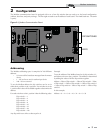
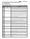
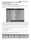
Modbus Instructions
The Modbus communication board is equipped with a set of ten dip switches that are used to set the board configuration
(address, baud rate, and parity settings). The first eight are used to set the address of each board. The ninth baud rate. The tenth
is parity.
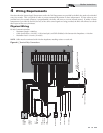
LED’S
DIP SWITCHES
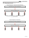
Figure 2-1_Modbus Communication Board