


9
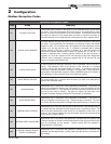
Modbus Instructions
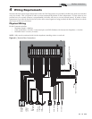
4 Wiring Requirements
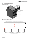
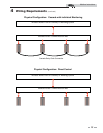
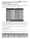
RS-485 Communication Bus
• Maximum Length = 4000 feet
• Cable Specification = 24 AWG / A,B (twisted pair) and GND Shielded, with characteristic Impedance = 120 ohm
• Maximum Load = 32 units (32 nodes)
NOTE: Cable must be terminated with 120 ohm impedance matching resistor on each end.
Note that when the System Supply Temperature and/or the Tank Temperature are provided by the BAS, they need to be refreshed
every few seconds. This is required in order to prevent unwanted fluctuations in these temperatures. If these values are not
provided every few seconds (timeout is programmable), the boiler will revert to its own internal control. If neither of these
temperatures is provided by the BAS, but any of the other control signals are being provided, the BAS will still need to refresh
these inputs at least every 4 minutes.
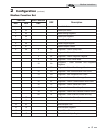
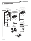
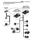
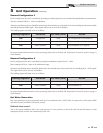
Physical Wiring
Figure 4-1_Terminal Strip Connections
1 ALARM
LBL20052 REV B
30 SHIELD GND
MOD BUS
0 - 10V INPUT
2 CONTACTS
3 RUN TIME
4 CONTACTS
5 LOUVER
6 PROVING
8 FLOW SWITCH
10 FLOW SWITCH
29 A
26 SENSOR
25 TANK
24 SENSOR
23 OUT DOOR
22 SENSOR
21 SYSTEM
20 (-)
19 (+)
18 SHIELD GND
17 B
16 A
15 SHIELD GND
14 W
13 R
11 TANK
12 THERMOSTAT
28 B
27 SHIELD GND
CASCADE
ENABLE
A
B
A
B
A
B
BUILDING
MANAGEMENT
SYSTEM
LOUVER
PROVING
SWITCH
TANK
THERMOSTAT
ENABLING DEVICE
SYSTEM SENSOR
OUTDOOR SENSOR
TANK SENSOR
SHIELD
SHIELD
FROM PREVIOUS BOILER
TO NEXT BOILER
SHIELD
HEAT
EXCHANGER 2
FLOW SWITCH
HEAT
EXCHANGER 1
FLOW SWITCH
A
B
SHIELD
MODBUS COMMUNICATION BUS
TO NEXT BOILER
9 HEX 1
7 HEX 2