


16
5 Unit Operation
Cascade
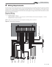
In order to operate the SYNC boiler in Cascade with Modbus
communications, configure the leader boiler per the demand
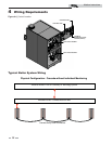
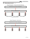
configurations in this manual. Connect the remaining boilers
in the cascade through the normal cascade communications
wiring. Cascade control can then be accomplished
automatically through the leader boiler.
Please note that with Modbus communication connected to
only the leader boiler, total Cascade information can be seen
through the communications link. If you wish to see all the
individual temperatures of each unit in the Cascade, each unit
will have to have a Modbus communication board. However,
each unit can be monitored without the need to control each
one individually.
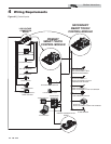
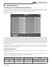
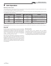
DHW with remote control:
This installation may or may not have the hot water generator in close proximity to the boiler. Its sensors and thermostat values
are only available through the Modbus communication bus.
To ensure that the SYNC boiler can properly respond to a call for hot water generation the following holding registers must be
set in addition to other commands:
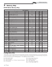
Holding Registers Definition Bit Value (HEX) Action
40001
Configuration 00 4A Set Configuration to read 40002, 4 & 5
40002
Coils 00 08 Enables Tank Tstat (00 00 disables unit)
40004
Tank Setpoint 0# ## Sets Setpoint
40005
Tank Temperature 0# ## Passes tank temp from remote sensor
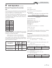
For proper hexadecimal conversion of rate percentage, please refer to the Rate and Temperature Conversion section on page 17
of this manual.
NOTE: To ensure proper operation re-send the configuration bits to holding register 40001 prior to issuing a command.
Modbus Instructions
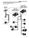
Monitoring Only
Any SYNC boiler can be equipped with the Modbus
communication board and then be set up to operate with its
own internal controls. If necessary, Modbus can be configured
as a monitoring device by selecting demand configurations 1 -
3, and polling the Modbus board for the read only variables.