


19
6 Troubleshooting (continued)
Lockout Codes (Input Registers 30016 and 30025)
161 = EEPROM code Parameters not Re-Programmed by
Lochinvar
164 = EEPROM code No Reset Allowed (> 15 minutes)
166 = EEPROM code Auto Reset High Limit
167 = EEPROM code Blocked Drain
168 = EEPROM code Louver Proving
169 = EEPROM code Gas Pressure Sw
170 = EEPROM code Flow Switch
177 = Sensor 3 short (Flue Sensor)
178 = Sensor 3 open (Flue Sensor)
179 = Sensor 2 short (Inlet Sensor)
180 = Sensor 2 open (Inlet Sensor)
192 = Sensor 1 short (Outlet Sensor)
193 = Sensor 1 open (Outlet Sensor)
204 = CRC EEPROM failed
205 = EEPROM programmed (display shows “PP”)
206 = EEPROM error in programming
207 = Write error EEPROM
229 = EEPROM code Watch Dog
230 = EEPROM code fan low (should be high)
231 = EEPROM code fan high (should be low)
232 = EEPROM code no flame when running
233 = EEPROM code no flame after ignition
234 = EEPROM code simultaneous output APS and Fan
235 = EEPROM code APS active not Closed
236 = EEPROM code APS active not Open
237 = EEPROM code flame out of sequence
239 = EEPROM code when gas valve relay test fails
240 = EEPROM code MRHL
32767 = Code not present
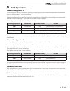
Modbus Instructions
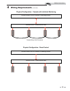
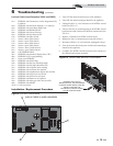
Installation / Replacement Procedure
1
3
2
UNPLUG THREE (3) WIRE HARNESSES
Figure 6-1_MTR01 Control Board
1. Turn OFF the main electrical power to the appliance.
2. Turn OFF the main manual gas shutoff to the appliance.
3. Unplug the three (3) wire harnesses on the MTR01 control
board (see FIG. 6-1).
4. Unscrew the four (4) mounting nuts on the MTR01 control
board and set aside. Remove the MTR01 control board (see
FIG. 6-2).
5. Replace / install the new MTR01 control board.
6. Replace the four (4) mounting nuts removed in Step 4.
7. Reconnect all three (3) wire harnesses unplugged in Step 3.
8. Turn on the main electrical power and the main manual gas
shutoff to the appliance.
9. Configure the MTR01 control board and unit controls per
this manual and resume operation.
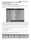
UNSCREW THE FOUR (4)
MOUNTING NUTS ON THE MODBUS
CONTROL BOARD (MTR01) AND SET
ASIDE TO SECURE THE
NEW MTR01 CONTROL BOARD
TO THE CONTROL PANEL
Figure 6-2_Control Panel w/MTR01 Control Board