


14
5 Unit Operation
Unit Operation with Modbus Communications
To control a SYNC boiler through a Building Management System communicating through Modbus, the SYNC Demand
Configuration must be set to a value of 4, 5, or 6. These configurations allow different control points for a variety of applications.
The configuration can be set by selecting Main>>Setup>>Service/Setup>>Demand Config.
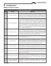
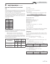
Holding Registers Definition Bit Value (HEX) Action
40001
Configuration 00 01 Set Configuration to read 40002
40002
Coils 00 01 Enables unit (00 00 disables unit)
NOTE: To ensure proper operation re-send the configuration bits to holding register 40001 prior to issuing a command.
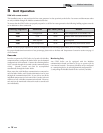
The SYNC boiler is equipped with a Modbus communication timer. This timer is programmable from 0 - 120 seconds. The timer
can be programmed from the Modbus Setup Menu by selecting Main>>Setup>>BMS>>Modbus Timeout. The purpose of the
timer is to ensure proper temperature data is communicated to the boiler in a timely manner. Additionally, it will provide for fail
safe operation should Modbus communication be lost. This timer will cause the unit to revert back to internal unit controls
should the Modbus communication be interrupted longer than the Modbus timer. The timer is reset every time a Modbus write
command is received with updated temperatures or commands. It is the recommendation of Lochinvar that this timer be set to
the shortest value possible.
When controlling a SYNC boiler through a Building Automation System (BAS), it is very important to ensure that the correct
configuration bits are sent to holding register 40001, and that the correct data and enable signals are sent to holding registers
40002 - 40007, per the demand configuration.
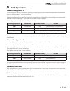
Demand Configuration 4
In this configuration the unit is controlled by setting the setpoints locally on the boiler and providing an enable signal through
Modbus communications.
All sensors and limiting devices should be hardwired to the terminal strip on the back of the unit excluding the thermostat enable
and tank thermostat enable signal. These signals will be sent to the unit via Modbus.
The holding registers will need to be set as follows:
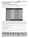
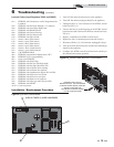
Figure 5-1_Setup Screen
Modbus Instructions