


Installation & Operation Manual
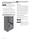
Low voltage connections
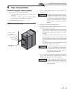
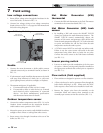
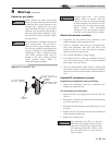
1. Route all low voltage wires through the knockouts in the
rear of the boiler, as shown in FIG. 7-2.
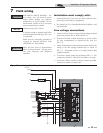
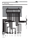
2. Connect low voltage wiring to low voltage connection
board as shown in FIG. 7-3 on page 38 of this manual and
the boiler wiring diagram.
LOW VOLTAGE
CONNECTION BOARD
LOW VOLTAGE
WIRING KNOCKOUTS
LINE VOLTAGE
WIRING KNOCKOUTS
Figure 7-2 Routing Field Wiring
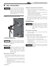
7 Field wiring
Enable
1. Connect the room thermostat or boiler enable contacts
(isolated contact only) to terminals R and W, as shown in
FIG. 7-3.
2. If a thermostat is used, install the thermostat on the inside
wall away from influences of drafts, hot or cold water
pipes, lighting fixtures, television, sunlight, or fireplaces.
3. Thermostat anticipator (if applicable):
a. If connected directly to boiler, set for 0.1 amps.
b. If connected to relays or other devices, set to match
total electrical power requirements of connected
devices. See device manufacturers’ specifications
and thermostat instructions for details.
Outdoor temperature sensor
1. Connect the outdoor temperature sensor (FIG. 7-3) to the
Outdoor Sensor terminals on the connection board to
enable outdoor reset operation of the SYNC.
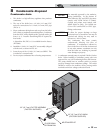
2. Mount the sensor on an exterior wall, shielded from direct
sunlight or flow of heat or cooling from other sources.
3. Route sensor wires through a knockout at the rear of the
boiler (see FIG. 7-2).
Hot Water Generator (HW)
thermostat
1. Connect the HW tank thermostat to the Tank Thermostat
terminals on the connection board (FIG. 7-3).
Hot Water Generator (HW) tank
sensor
1. By installing a HW tank sensor, the SMART TOUCH
control can perform the tank thermostat function. The
SMART TOUCH control automatically detects the
presence of this sensor, and generates a HW call for heat
when the tank temperature drops 6°F (3°C) below the tank
set point, and finishes the call for heat when the tank
temperature reaches the tank set point.
2. A TST2032 sensor MUST be used with any indirect tank.
Failure to use the correct sensor will result in the tank
temperature being either above or below the set point.
Connect the correct sensor to the Tank Sensor terminals
(see FIG. 7-3).
Louver proving switch
1. Louvers are used to provide combustion air for the room
air option. A louver proving switch should be installed on
the appropriate terminals and verified prior to operation
(see FIG. 7-3).
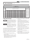
Flow switch (field supplied)
1. Flow switches are designed to prevent a no flow situation.
2. A flow switch may be used to guarantee flow through the
boiler before allowing it to fire. When used, the SYNC
boiler requires a flow switch to be installed on each inlet.
3. Remove the jumper wires from the terminals on the
connection board and connect these terminals to the
normally open contacts on the flow switches (FIG. 7-3).
36