


Installation & Operation Manual
23
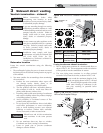
4 Vertical direct venting
Vent/air termination – vertical
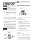
Prepare roof penetrations
1. Air pipe penetration:
a. Cut a hole for the air pipe. Size the air pipe hole as
close as desired to the air pipe outside diameter.
2. Vent pipe penetration:
a. Cut a hole for the vent pipe. For either combustible
or noncombustible construction, size the vent pipe
hole with at least a 1/2 inch clearance around the vent
pipe outer diameter:
• 7½ inch (178 mm) hole for 6 inch (152 mm) vent
pipe
• 8½ inch (203 mm) hole for 7 inch (178 mm) vent
pipe
b. Insert a galvanized metal thimble in the vent pipe
hole (when required by local codes).
3. Space the air and vent holes to provide the minimum
spacing shown in FIG.’s 4-1 and 4-2.
4. Follow all local codes for isolation of vent pipe when passing
through floors, ceilings, and roofs.
5. Provide flashing and sealing boots sized for the vent pipe
and air pipe.
Termination and fittings
1. Prepare the vent termination coupling and the air
termination elbow (FIG.’s 4-1 and 4-2) by inserting the bird
screens provided with the boiler.
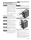
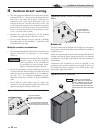
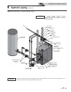
2. The air piping must terminate in a down-turned 180°
return bend as shown in FIG.’s 4-1 and 4-2. Locate the air
inlet pipe no further than 2 feet (.6 m) from the center of
the vent pipe. This placement avoids recirculation of flue
products into the combustion air stream.
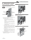
ALTERNATE INTAKE LOCATIONS:
INTAKE PIPES MAY BE LOCATED
ANYWHERE WITHIN 24" (610 MM)
OF VENT PIPE
BIRD SCREEN
(TYPICAL)
COUPLING
(FIELD SUPPLIED)
VENT OUTLET
12" MINIMUM
ABOVE AIR INLET
6" (152 MM) MINIMUM
ABOVE ROOF /
SNOW LINE
VENT
COMBUSTION
AIR
Figure 4-1 PVC/CPVC Vertical Termination of Air and
Vent
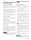
5. Locate terminations so they are not likely to be damaged by
foreign objects, such as stones or balls, or subject to buildup
of leaves or sediment.
ƽ WARNING
Rooftop vent and air inlet terminations
must terminate in the same pressure zone.
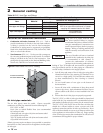
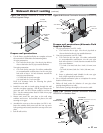
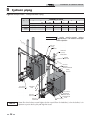
6" (152 MM) MINIMUM
ABOVE ROOF /
SNOW LINE
VENT
COM,BUSTION
AIR
ALTERNATE INTAKE LOCATIONS:
INTAKE PIPES MAY BE LOCATED
ANYWHERE WITHIN 24” (610 MM)
OF VENT PIPE
VENT OUTLET
36” (914 MM) MINIMUM
ABOVE AIR INLET
BIRD SCREEN
(TYPICAL)
Figure 4-2 Stainless Steel Vertical Termination of Air and
Vent
Follow instructions below when determining
vent location to avoid possibility of severe
personal injury, death or substantial
property damage.
Installation must comply with local
requirements and with the National Fuel Gas
Code, ANSI Z223.1 for U.S. installations or
CSA B149.1 or B149.2 for Canadian
installations.
ƽ WARNING
NOTICE
ƽ WARNING
Do not connect any other appliance to the
vent pipe or multiple boilers to a common
vent pipe. Failure to comply could result in
severe personal injury, death, or substantial
property damage.
Determine location
Locate the vent/air terminations using the following guidelines:
1. The total length of piping for vent or air must not exceed the
limits given in the General Venting Section on page 18 of
this manual.
2. The vent must terminate at least 3 feet above the highest
place in which the vent penetrates the roof and at least 2 feet
above any part of a building within 10 horizontal feet.
3. The air piping must terminate in a down-turned 180° return
pipe no further than 2 feet (.6 m) from the center of the vent
pipe. This placement avoids recirculation of flue products
into the combustion air stream.
4. The vent piping must terminate in an up-turned coupling as
shown in FIG. 4-1. The top of the coupling must be at least
1 foot above the air intake. When the vent termination uses
a rain cap as illustrated in FIG. 4-2 maintain at least 36"
(914 mm) above the air inlet. The air inlet pipe and vent
pipe can be located in any desired position on the roof, but
must always be no further than 2 feet (.6 m) apart and with
the vent termination at least 1 foot above the air intake.