


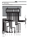

Installation & Operation Manual
General
How the boiler operates
The SYNC uses advanced stainless steel heat exchangers and
electronic control modules that allow fully condensing
operation. The blowers pull in air and push flue products out
of the boiler through the heat exchangers and flue piping. The
control modules regulate blower speed to control the boiler
firing rate. The gas valve senses the amount of air flowing into
the boiler and allows only the right amount of gas to flow.
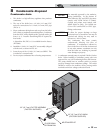
How the control modules operate
The SYNC boiler is equipped with two (2) SMART TOUCH
control modules. The control modules work in
synchronization to meet the heat demand of the system.
The SMART TOUCH control modules receive input from
boiler sensors and external inputs. The control modules
activate and control the blowers and gas valves to regulate heat
input and switches the boiler, Hot Water Generator (HW),
and system pumps on and off as needed. The user programs
the modules to meet system needs by adjusting control
parameters. These parameters set operating temperatures and
boiler operating modes. Boiler operation is based on system
temperature.
Control inputs and outputs
Room thermostat / zone control
This input tells the boiler to provide water for space heating.
Hot Water Generator (HW) tank thermostat
This input tells the boiler to provide water for heating an
indirect HW tank.
0 - 10V input (set point or power)
The SYNC can be controlled by a Building Management
System (BMS) using a 0 - 10 VDC signal. The control can be
configured by the installer to use this signal to either control
set point or firing rate.
HW priority
The SMART TOUCH control module allows connection of a
HW thermostat to the low voltage connection board. When the
HW thermostat calls for heat, the modules activate the HW
pumps, shuts down the boiler pumps, and immediately sets the
target outlet water temperature to 180°F (82.2°C). This provides
automatic priority heat allocation to the HW Generator for
maximum response and recovery. The HW pumps continue for
30 seconds after the heating cycle to deliver the most possible
heat.
Controlling sensor
The control module is programmed to use the outlet sensor as
the control sensor by default. If a system supply sensor is
connected, the control automatically uses it as the control
sensor.
Anti-cycling
After a space heating demand has been satisfied, the control will
delay the next space heating call for a set time period (time is
adjustable by the installer). The time delay will be bypassed if
the inlet water temperature drops too far during the delay.
Boiler, system, and HW pump control
When a space heating call for heat starts and no HW call is on,
the system and boiler pumps are turned on. As long as the space
heating call for heat is on, the system pump will remain on. If a
HW call for heat is on, the boiler pumps will wait to turn on
until just before the HW pumps turn off. After the space heating
call for heat ends, both pumps will run for an additional period
of time.
When a HW call for heat starts, the HW pumps are turned on.
If a space heating call for heat was on, the boiler pumps will turn
off a few seconds after the HW pumps turn on.
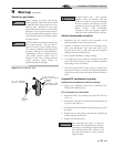
Louver
A dry contact is provided to open and close louvers whenever
the SYNC boiler requires combustion air from inside the room.
Connect the Louver End Switch to the Louver Proving Switch
input on the Low Voltage Connection Board.
Temperature control
Modulation
The SYNC is capable of modulating its firing rate from a
minimum of 10% to a maximum of 100%. The firing rate is
dictated by the call for heat (i.e., space heating or hot water
generation), the heating load, and various other temperature
limitations.
10 Operating information
46