


Installation & Operation Manual
9 Start-up
Check flame and combustion (continued)
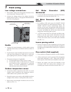
4. Navigate to the Service Mode Screen from the Status
Screen by pressing the MAIN button and then the
SERVICE MODE button.
5. On the Service Screen place the Primary Module into
operation by selecting Module 1 with the SELECT button
and turning the module on by pressing the ON/OFF
button (OFF indicates that the module is off and ON
indicates that the module should be firing).
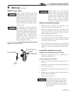
6. Insert the probe from a combustion analyzer into the hole
left by the removal of the flue temperature sensor.
Note:
The Primary Module is the top module; please
ensure the probe is in the top flue sensor location.
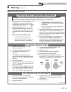
7. Once the module has modulated up to full fire measure
the combustion. The values should be in the range listed
in Table 9A below. CO levels should be less than 200 ppm
for a properly installed unit. If the combustion is not
within range reference the Troubleshooting Section in the
SYNC Service Manual for possible causes and corrective
actions.
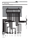
Set space heating operation
Verify space heat circulator mode
The Space Heating Mode controls the system pump (if
connected), and both boiler pumps. When the SMART
TOUCH control receives a space heating call for heat, it turns
on the system pump. If the boiler is not heating an indirect HW
(Hot Water) tank, it also turns on the boiler pump. After the
space heating call for heat ends, the system pump continues to
run for a short period of time. If the boiler pump was running,
it continues to run for a short period of time as well. These
pump delays are factory set to 30 seconds. If different delays are
desired, the appropriate parameters in the control must be
changed. See the SYNC Service Manual for a detailed
explanation of this procedure.
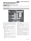
Set space heating set point temperature
During normal operation, space heating set point temperatures
can be adjusted from the Set Points Menu. Press the following
buttons to navigate to the Set Points Menu from the Status
Screen:
1. To change a set point, press the SELECT button next to the
user set point parameter.
2. The first time the user set point parameter is accessed, you
will be required to enter the user password. The user
password is 0704.
3. Using the keypad, enter the password and then press the
OK button. If the password is not entered correctly, the
screen will revert to the Parameter List Screen and you will
not be able to adjust the set point. If a digit has been
entered incorrectly, press the left arrow key on the keypad
to back the digit up. If the password has been entered
correctly, the Parameter Change Screen will appear. The
Parameter Change Screen will display the set point being
changed, the previous setting of the set point, and
adjustment buttons.
4. To adjust the set point, press the + or - buttons to change
the value being displayed.
5. Once the set point has been adjusted to the desired
setting press the APPLY button to change the set point
and return to the Parameter List Screen.
Table 9A Flue Products Chart
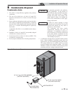
8. Once the Primary Module analysis is complete, test the
safety shutoff device by turning the manual shutoff valve
to the OFF position and ensuring that the Primary
Module shuts down and registers an alarm. Open the
manual shutoff valve, reset the control, and return to
Service Mode.
9. Repeat the same procedure for the Secondary Module by
selecting Module 2 while on the Service Mode Screen. Be
certain to insert the probe from the combustion analyzer
into the Secondary Module flue temperature sensor
location.
10. Turn the main power off to the boiler and replace the
flue temperature sensor into the flue pipe connection.
11. Place the boiler back into normal operation.
You must replace the flue gas temperature
sensor to prevent flue gas spillage into the
room. Failure to comply could result in
severe personal injury, death, or
substantial property damage.
ƽ WARNING
Natural Gas Propane
CO
2
O
2
CO
2
O
2
8.0% - 10% 3.0% - 6.5% 9.0% - 11% 4.1% - 6.9%
44
>> >>