


Troubleshooting
58
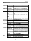
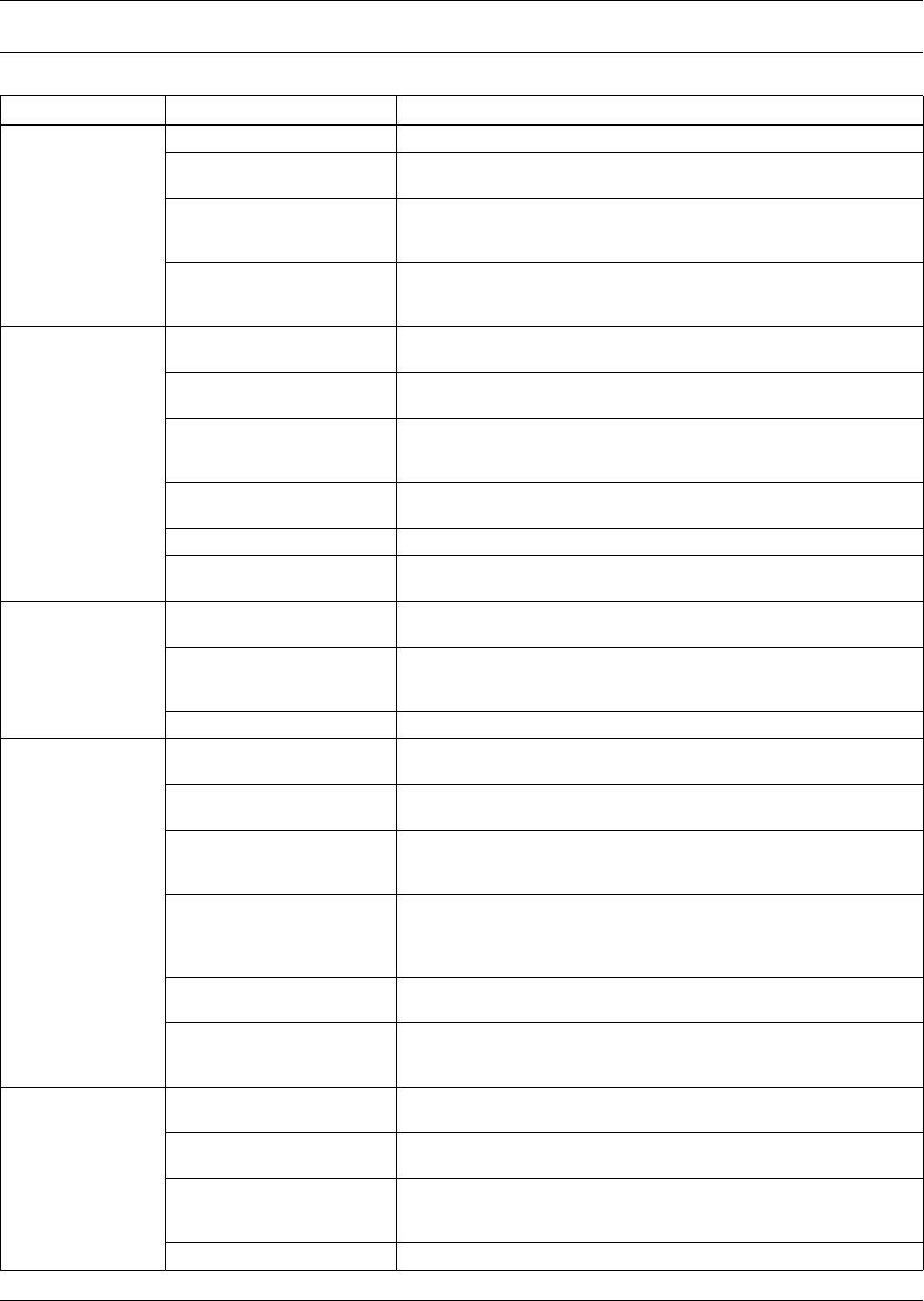
8.0 TROUBLESHOOTING
Table 18 Troubleshooting
Symptom Possible Cause Check or Remedy
Unit will not start
No power to unit Check voltage at input terminal block.
Control voltage fuses (at
transformer) open
Locate and repair short. Replace fuses.
Float switch relay has closed
due to high water in the
condensate pan.
Check drain and line. Access through left panel. Power must be
cycled at the disconnect to reset. Check return air static pressure is
less than 0.3" wg.
Jumper not in place
Check terminal 37 and 38 for jumper or N/C contact. Check pins P39-
1 and P39-2 for jumper, or N/C firestat contact. Check pins P40-12
and 1HWAR-Com for jumper or N/C smoke detector contact.
No cooling
“Cooling” is not displayed at
the control panel.
Adjust TEMP control setpoint and sensitivity to require cooling.
Short cycle prevention
control.
Control software delays compressor 3 minutes cooling, from stop to
start
Compressor contactor not
pulling in.
Check for 24 VAC ± 2 VAC at terminals TB2 to TB1 for Compressor 1;
TB6 to TB5 for Compressor 2. If voltage, check contactor. If voltage,
check freeze stat (FR1 and FR2).
Compressor high head
pressure.
See below for cause.
Plugged filter/dryer. Replace filter/dryer.
Low refrigerant charge.
Check pressure gauges. At low ambient temperatures, proper
refrigerant charge is very important on units with Lee-Temp receivers.
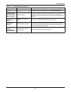
Compressor high
head pressure
Insufficient air flow across
condenser coil
Remove debris from coil and air inlets.
Water/Glycol-Cooled only:
No fluid flowing through
condenser.
Check fluid supply to regulating valve. Adjust valve if necessary.
Condenser fan not operating Check fan operation.
Humidifier does
not operate
DIP switch not set to enable
humidifier option
See DIP switch settings Table 17.
“HUMIDIFY” not displayed
at control panel
Increase humidity control setpoint and sensitivity to require
humidification.
Defective board
Check voltage at 35-1 and 35-5 on interface board for 24 VAC ±2
VAC. If no voltage, check wiring and/or replace board. Check wiring
from control panel to board.
Failed humidity sensor
Humidity display will indicate dashes. Check wiring from temperature/
humidity board to the control board and from the wall box to the
control board. Replace wallbox or temperature/humidity circuit board
(if remote).
No water flow
Make sure switch is in Run position. Check humidifier water supply
(including filter screen) and check nylon overflow line if canister is full.
Canister fill rate is not
keeping up with the steam
output
Check fill valve screen opening and capillary tube for obstructions.
Check water supply pressure (minimum 10 psig).
Reheat will not
operate
DIP switch not set to enable
reheat option
See DIP switch settings Table 17.
“HEAT” not displayed at the
control panel
Increase temperature setpoint to require heating.
Reheat safety open,
defective reheat contact or
defective board
Check voltage at P34-4 or P34-6 to P34-10 on interface board for 24
VAC
± 2 VAC. If voltage, check reheat contactor and reheat safety. If
no voltage, check wiring and/or replace board.
Element is burned out Turn off power. Check element continuity with Ohm meter.