


Site Preparation and Installation
4
2.0 SITE PREPARATION AND INSTALLATION
2.1 Installation Considerations
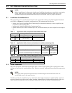
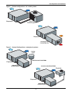
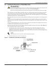
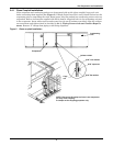
The evaporator unit is usually mounted above the suspended ceiling using field supplied threaded
rods. Refer to Figure 1 for possible configurations. The condensing unit may be:
• Indoor Air-Cooled Centrifugal Fan Condensing Unit mounted remotely or close coupled to the
evaporator in the ceiling space.
• Outdoor Air-Cooled Propeller Fan Condensing Unit.
• Indoor Water/Glycol-Cooled Condensing Unit, mounted remotely or close coupled to the evapora-
tor.
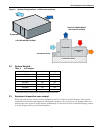
2.1.1 Room Preparation
The room should be well-insulated and must have a sealed vapor barrier. The vapor barrier in the
ceiling and walls can be a polyethylene film. Paint on concrete walls and floors should be vapor resis-
tant.
Outside or fresh air should be kept to a minimum when tight temperature and humidity control is
required. Outside air adds to the cooling, heating, dehumidifying and humidifying loads of the site.
Doors should be properly sealed to minimize leaks and should not contain ventilation grilles.
NOTE
Before installing unit, determine whether any building alterations are required to run piping,
wiring, and duct work. Carefully follow all unit dimensional drawings and refer to the
submittal engineering dimensional drawings of individual units for proper clearances.
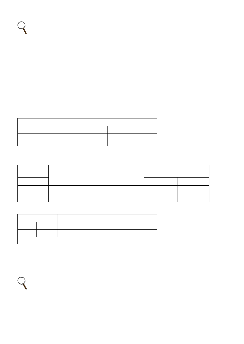
Table 1 Application limits, evaporator and chilled-water units*
Input Voltage Range of Return Air Conditions to Unit
Min Max Dry Bulb Temp. Relative Humidity
-5% +10%
65°F to 85°F
(18
°C to 29°C)
20% to 80%
*Unit will operate at these conditions but will not control to these extremes.
Table 2 Application limits, indoor and outdoor air-cooled condensing units
Input
Voltage
Condensing Units Entering Dry Bulb
Air Temperature
Min Max Min Max
-5% +10%
Outdoor Prop Fan Condensing Unit
Indoor Air-Cooled Centrifugal Condensing Unit
-30
°F (-34°C)
-20
°F (-29°C)
120
°F (49°C)
115
°F (46°C)
Table 3 Application limits, indoor water/glycol-cooled condensing units
Input Voltage Entering Fluid Temperature
Min Max Min Max
-5% +10% 65°F (18.3°C) * 115°F (46°C)
*Operation below 65°F (18°C) may result in reduced valve life and fluid noise.
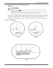
NOTE
The single most important requirement for maintaining environmental control in the
conditioned room is the vapor barrier.