


iv
FIGURES
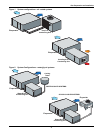
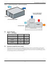
Figure 1 System configurations—air cooled systems. . . . . . . . . . . . . . . . . . . . . . . . . . . . . . . . . . . . . . . . . . . . 6
Figure 2 System Configurations—water/glycol systems . . . . . . . . . . . . . . . . . . . . . . . . . . . . . . . . . . . . . . . . . 6
Figure 3 System Configurations—chilled water systems . . . . . . . . . . . . . . . . . . . . . . . . . . . . . . . . . . . . . . . . 7
Figure 4 Threaded rod and hardware kit installation . . . . . . . . . . . . . . . . . . . . . . . . . . . . . . . . . . . . . . . . . . . 8
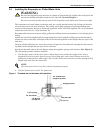
Figure 5 Close coupled installation. . . . . . . . . . . . . . . . . . . . . . . . . . . . . . . . . . . . . . . . . . . . . . . . . . . . . . . . . . 9
Figure 6 Drain installation . . . . . . . . . . . . . . . . . . . . . . . . . . . . . . . . . . . . . . . . . . . . . . . . . . . . . . . . . . . . . . . 11
Figure 7 Condensate pump installation . . . . . . . . . . . . . . . . . . . . . . . . . . . . . . . . . . . . . . . . . . . . . . . . . . . . . 12
Figure 8 General arrangement diagram - chilled-water systems . . . . . . . . . . . . . . . . . . . . . . . . . . . . . . . . . 13
Figure 9 Refrigerant piping diagram . . . . . . . . . . . . . . . . . . . . . . . . . . . . . . . . . . . . . . . . . . . . . . . . . . . . . . . 14
Figure 10 Evaporator or chilled-water unit dimensional data . . . . . . . . . . . . . . . . . . . . . . . . . . . . . . . . . . . . 16
Figure 11 Evaporator unit electrical connections . . . . . . . . . . . . . . . . . . . . . . . . . . . . . . . . . . . . . . . . . . . . . . 18
Figure 12 Piping connections - indoor air-cooled centrifugal fan condensing unit . . . . . . . . . . . . . . . . . . . . 20
Figure 13 Indoor air-cooled centrifugal condensing unit dimensions and pipe connections . . . . . . . . . . . . . 21
Figure 14 Indoor air-cooled centrifugal condenser electrical connections . . . . . . . . . . . . . . . . . . . . . . . . . . . 22
Figure 15 Electrical field connections - outdoor condensing unit . . . . . . . . . . . . . . . . . . . . . . . . . . . . . . . . . . 24
Figure 16 Footprint dimensions - outdoor condensing unit. . . . . . . . . . . . . . . . . . . . . . . . . . . . . . . . . . . . . . . 25
Figure 17 Piping and electrical connections - outdoor condensing unit . . . . . . . . . . . . . . . . . . . . . . . . . . . . . 26
Figure 18 Indoor water/glycol condensing unit dimensional data . . . . . . . . . . . . . . . . . . . . . . . . . . . . . . . . . 28
Figure 19 Indoor water/glycol condensing unit electrical field connections . . . . . . . . . . . . . . . . . . . . . . . . . . 29
Figure 20 System piping with indoor water/glycol-cooled condensing unit . . . . . . . . . . . . . . . . . . . . . . . . . . 30
Figure 21 Optional free cooling coil (3-way valve) on water/glycol units . . . . . . . . . . . . . . . . . . . . . . . . . . . . 31
Figure 22 Optional free cooling coil (3-way valve) on air-cooled units . . . . . . . . . . . . . . . . . . . . . . . . . . . . . . 32
Figure 23 Wall box . . . . . . . . . . . . . . . . . . . . . . . . . . . . . . . . . . . . . . . . . . . . . . . . . . . . . . . . . . . . . . . . . . . . . . . 34
Figure 24 Control menu. . . . . . . . . . . . . . . . . . . . . . . . . . . . . . . . . . . . . . . . . . . . . . . . . . . . . . . . . . . . . . . . . . . 43
Figure 25 Control board (inside evaporator) . . . . . . . . . . . . . . . . . . . . . . . . . . . . . . . . . . . . . . . . . . . . . . . . . . 44
Figure 26 Wall box board. . . . . . . . . . . . . . . . . . . . . . . . . . . . . . . . . . . . . . . . . . . . . . . . . . . . . . . . . . . . . . . . . . 44
TABLES
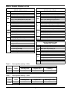
Table i Heat rejection matchup – 60 Hz. . . . . . . . . . . . . . . . . . . . . . . . . . . . . . . . . . . . . . . . . . . . . . . . . . . . . v
Table ii Heat rejection matchup – 50 Hz. . . . . . . . . . . . . . . . . . . . . . . . . . . . . . . . . . . . . . . . . . . . . . . . . . . . . v
Table 1 Application limits, evaporator and chilled-water units* . . . . . . . . . . . . . . . . . . . . . . . . . . . . . . . . . 4
Table 2 Application limits, indoor and outdoor air-cooled condensing units . . . . . . . . . . . . . . . . . . . . . . . . 4
Table 3 Application limits, indoor water/glycol-cooled condensing units . . . . . . . . . . . . . . . . . . . . . . . . . . . 4
Table 4 Unit weights . . . . . . . . . . . . . . . . . . . . . . . . . . . . . . . . . . . . . . . . . . . . . . . . . . . . . . . . . . . . . . . . . . . . 7
Table 5 Evaporator external static pressure (60) at 3750 CFM (6371 CMH). . . . . . . . . . . . . . . . . . . . . . . 10
Table 6 Recommended refrigerant line sizes . . . . . . . . . . . . . . . . . . . . . . . . . . . . . . . . . . . . . . . . . . . . . . . . 14
Table 7 8-ton unit refrigerant charge . . . . . . . . . . . . . . . . . . . . . . . . . . . . . . . . . . . . . . . . . . . . . . . . . . . . . . 15
Table 8 Line charges (field piping)* . . . . . . . . . . . . . . . . . . . . . . . . . . . . . . . . . . . . . . . . . . . . . . . . . . . . . . . 15
Table 9 Refrigerant quick connect sizes and torque. . . . . . . . . . . . . . . . . . . . . . . . . . . . . . . . . . . . . . . . . . . 15
Table 10 Default setpoints and allowable ranges. . . . . . . . . . . . . . . . . . . . . . . . . . . . . . . . . . . . . . . . . . . . . . 36
Table 11 Night and weekend setback plan . . . . . . . . . . . . . . . . . . . . . . . . . . . . . . . . . . . . . . . . . . . . . . . . . . . 37
Table 12 Setup functions, default values and allowable ranges . . . . . . . . . . . . . . . . . . . . . . . . . . . . . . . . . . 39
Table 13 Alarm default time delays . . . . . . . . . . . . . . . . . . . . . . . . . . . . . . . . . . . . . . . . . . . . . . . . . . . . . . . . 40
Table 14 Equipment switch settings (unit control board) . . . . . . . . . . . . . . . . . . . . . . . . . . . . . . . . . . . . . . . 41
Table 15 Switch settings (wallbox board) . . . . . . . . . . . . . . . . . . . . . . . . . . . . . . . . . . . . . . . . . . . . . . . . . . . . 41
Table 16 Typical discharge pressures . . . . . . . . . . . . . . . . . . . . . . . . . . . . . . . . . . . . . . . . . . . . . . . . . . . . . . . 52
Table 17 Humidifier control board DIP switch settings. . . . . . . . . . . . . . . . . . . . . . . . . . . . . . . . . . . . . . . . . 56
Table 18 Troubleshooting. . . . . . . . . . . . . . . . . . . . . . . . . . . . . . . . . . . . . . . . . . . . . . . . . . . . . . . . . . . . . . . . . 58