


Site Preparation and Installation
22
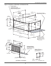
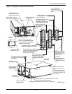
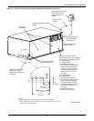
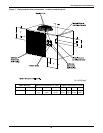
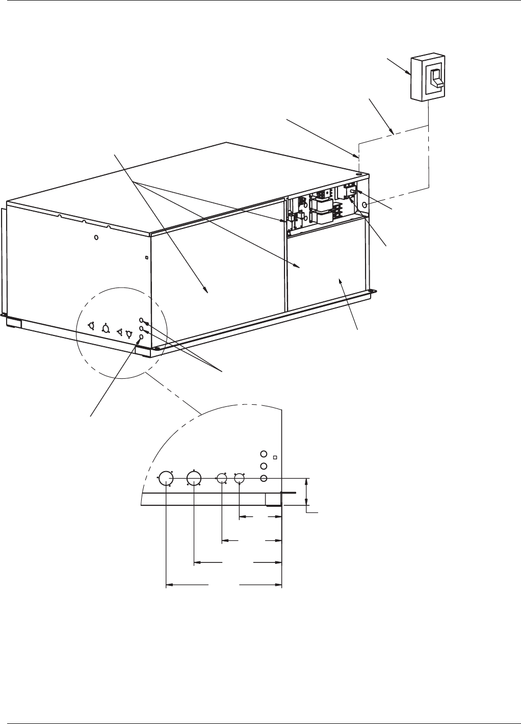
Figure 14 Indoor air-cooled centrifugal condenser electrical connections
Removable
Access Panels
Connection Terminal for
Field Supplied Earth
Grounding Wire.
Line Voltage
Electric Power Supply
Conduit.
Openings for Field Supplied
24V NEC Class 2 Wiring
Between Condensing Unit and
Fan/Coil Unit.
Low VoltageElectric Power
Supply Conduit Entrance.
Field Supplied Unit Disconnect
Switch when Factory Unit
Disconnect Switch is not
Supplied.
Electric Service not
by Liebert.
Optional Factory Installed
Disconnect Switch.
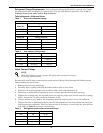
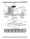
6"
8 1/2 "
12 1/2 "
16 1/2 "
4"
(101.6mm)
(152.4mm)
(215.9mm)
(317.5mm)
(419.1mm)
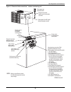
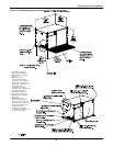
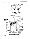
Heat rejection connection
.
Field
supplied 24V NEC class 2 wiring. See note 2.
Wire connections from evaporator module:
1. 24V GND System 1
2. 24V Supply System 1
3. High Pressure Alarm System 1
4. Hot Gas Bypass Connection System 1
(only on units with hot gas bypass.
If no hot gas bypass, connection is
provided in the evaporator module.
Connect wire 4 and wire 2 to the
24V supply).
5. 24V GND System 2
6. 24V Supply System 2
7. High Pressure Alarm System 2
8. Hot Gas Bypass Connection System 2
(only on units with hot gas bypass.
If no hot gas bypass, connection is
provided in the evaporator module.
Connect wire 8 and wire 6 to the
24V supply).
9. 24V GND Condenser Fan
10. 24V SUPPLY Condenser Fan
NOTES:
1. Refer to specification sheet for full load amp. and wire size amp. ratings.
2. Control voltage wiring must be a minimum of 16 GA (1.6mm) for up to 75’ (23m) or not
to exceed 1 volt drop in control line.
DPN000249_Rev0