Microprocessor Control
41
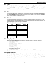
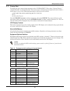
3.17 Custom Text
To modify the two custom alarm messages select “CUSTOM TEXT”. Then select “Custom Text #1,”
“Custom Text #2” or “Custom Text #3.” Text can be up to 16 characters in length and can be either a
blank space or any of the following alphanumeric characters and symbols:
• A,B,C,D,E,F,G,H,I,J,K,L,M,N,O,P,Q,R,S,T,U,V,W,X,Y,Z
• #,%,*,-
• 0,1,2,3,4,5,6,7,8 or 9
Use the UP/DOWN arrows to select a character, then press ENTER. The cursor will move to the
next space where you may once use the UP/DOWN arrows to select another character, etc. The cus-
tom text alarm will be displayed only if the alarm is selected in Custom Alarms.
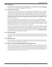
LCD Display Contrast
The level of contrast due to the viewing angle of the LCD display can be adjusted using a potentiome-
ter screw, inside the wall box next to the display.
Nonvolatile Memory
All critical information is stored in nonvolatile memory. Setpoints and setup parameters are kept
inside the microcontroller in EEPROM.
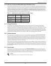
Equipment Options Switches
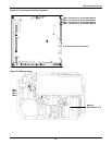
Equipment options are selected and enabled using DIP switches 1 through 7. These are located on the
control board near TB3. These switches are factory set and should not require any user changes. The
setting and function of the switches can be individually read on the LCD display.
NOTE
In order to update the DIP switch settings, power must be cycled off, then on, from the unit
disconnect switch.
Table 14 Equipment switch settings (unit control board)
Switch OFF Position ON Position
1 Step Cool Ramp Cool
2 Step Heat Ramp Heat
3 Not Used Not Used
4 No GLYCOOL GLYCOOL
5 Disable 1 stage CW Enable 1 stage CW
6 Not used Not used
7 1-stage
dehumidification
2-stage
dehumidification
8 Disable SCR Reheat Enable SCR Reheat
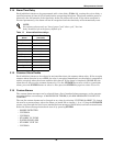
Table 15 Switch settings (wallbox board)
Switch OFF Position ON Position
1 Beeper Disable Beeper Enable
2 Not Used Not Used
3 Not Used Not Used
4 Enable Reheat Disable Reheat
5 Enable Hum. Disable Hum.
6 Enable Dehum. Disable Dehum.
7 Disable Setback Enable Setback
8 Enable Password Disable Password


