Site Preparation and Installation
12
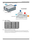
Condensate Pump
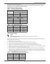
The optional condensate pump kit is required when the evaporator is installed below the level of the
gravity-fed drain line. Refer to the installation instructions provided with the condensate pump kit.
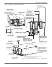
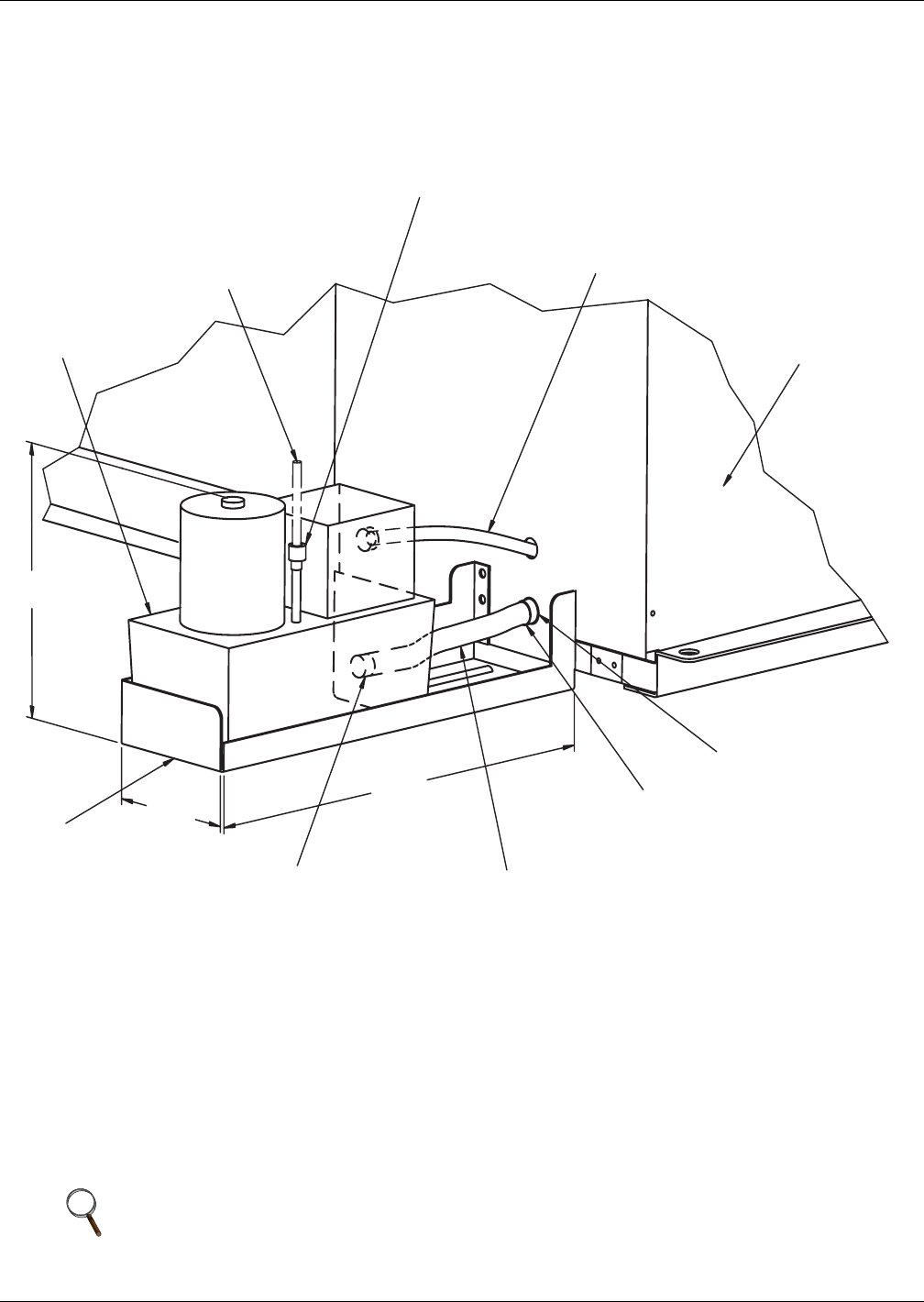
Figure 7 Condensate pump installation
Humidifier Water Supply Line
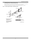
Units supplied with the optional humidifier package have a 1/4 in. (6.4 mm) FPT connection for water
inlet. Supply pressure range is 10 psig to 150 psig. Required flow rate is 1 gpm. A shut-off valve
should be installed in this line to isolate the humidifier for maintenance.
NOTE
DO NOT route humidifier supply line in front of filter box access panel.
Condensate Pump
Condensate
Pump
Support Bracke
t
3/4" (13mm)
Hose Barb
Supplied on Pump Tank
Flexible Rubber Tubing
3/4" (13mm) FPT
Customer Connection
Condensate Drain
Evaporator or
Chilled Water
Unit
Power Supply from
Electric Service Power
Block in Fan/Coil Module.
Drain Line
(field supplied)
Notes:
1. 3/4" (13mm) Flexible Rubber Tubing Assembly (Supplied
with Pump Kit) must be installed on pump end.
2. The High Water Safety Float included with pump must be
interlocked with unit control. Wire to terminals 60 & 61 on
Evaporator terminal strip to shut down unit.
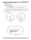
3/8" Compression Fitting
Drain Connection
FRONT OF UNIT
AIR INLET
21 1/2 "
6 5/8 "
10 9/16 "
(268.3mm)
(168.3mm)
(546mm)
DPN000239_Rev0


