16
millivolt Control system
This insert operates on a millivolt control system. As such, no
addition power supply is needed for the insert to operate. The
pilot assembly contains a Thermopile, that when heated by the
pilot flame, generates electricity (millivolts, mV=1/1000 of a volt)
that travels to terminal #1. From this terminal it travels through
a black wire to the Vent Safety Snap Switch. If this switch over-
heats through a flue blockage or vent pipe disconnection it will
open, stop the flow of mV and shut the insert off. This switch will
automatically reset (close), when it is cooled down to normal
operating temperature. During normal operation, it is closed
allowing the mV to flow back to the valve, which opens so gas
can flow through.
To check for proper operation, use a multimeter and perform the
system checks shown in Table 4 (and refer to Figure 19).
Thermostat Wire
Wire Size Maximum Length
12 Gage
100 Feet
14 Gage 64 Feet
16 Gage 40 Feet
18 Gage 25 Feet
20 Gage
16 Feet
Table 3
Do not splice any millivolt wires. Refer to Table 3 to determine
the proper gage of wire for the thermostat or wall switch
connections. This table refers to the total length of the wire
(out to the switch and back). The thermostat must be a
millivolt type. A 24-volt furnace thermostat will not work.
Never hook up household current, 120 Volts, to the millivolt
system. It is not recommended to hook up any more than
two switches to the insert (for example a rocker switch and a
wall thermostat). Additional switches may affect the system
resistance and increase the chance of the burner not ignit
-
ing. Follow the instructions included with the thermostat or
remote control for wiring.
The thermostat, remote control, and rocker switch will turn
the burner on and off independently. Be sure to set the rocker
switch to the “OFF” position when using the thermostat or
remote control and set the thermostat or remote control to
the lowest temperature when you wish to use the rocker
switch only, otherwise one may override the other. If a re
-
mote thermostat is to be used with the insert, do not place
the receiver under the firebox.
Millivolt and System Checks
Check
Test
To
Test
Connect
Meter
Leads to
Terminals
Thermostat
Connects
Meter
Reading
Should Be
A Complete
System
2 & 3 Closed 100 MV
or More
B Thermopile
Output
1 & 2
Open Greater
Than
325 MV
C System
Resistance
1 & 3 Closed 80 Ohms
Table 4
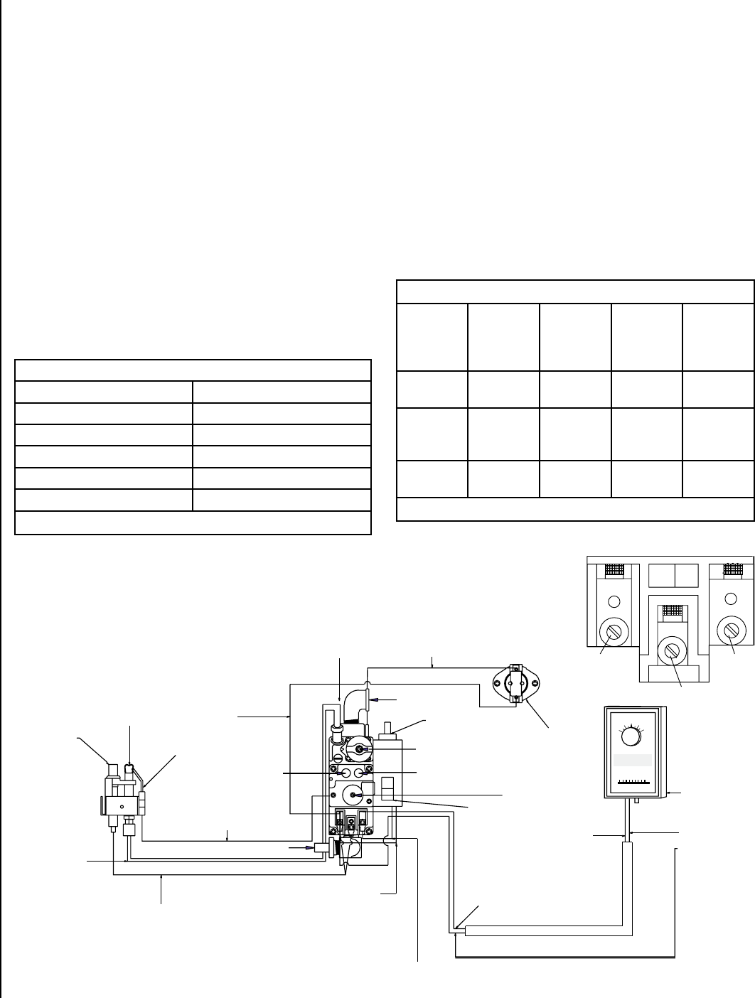
Figure 19
Thermopile
Pilot Hood
Pilot Tube
Spark Electrode
Terminal Snap Switch
Wire (Black SS1)
Spark Electrode Wire
(Black) connect to
Piezo Igniter
Burner Orifice
Thermopile Wire (Brown)
Connect to Terminals 1 & 2
On Gas Valve
On/Off Switch Wire
(Black) 001 Connect
Terminal 1 Gas Valve
Inlet Pressure
Tap
Gas Valve
Valve Snap Switch
Wire (Black) SS2
Inlet
Elbow
Piezo Igniter
On/Off Switch Wire (Black) 002 - Connect Terminal 3 Gas Valve
Off/On/Pilot
Manifold
Pressure Tap
Flame Adjustment
On/Off
Switch
Thermostat
Wire
(White) TH2
Thermostat
Wire
(Red) TH1
OPTIONAL
Thermostat
Vent Safety Snap
Switch
50
60
70
80
90
50
60
70
80
90
Terminal 2
TP
Terminal 3
TH
TH
TP
TH
Terminal 1
TH/TP
Valve Terminals
millivolt wiring diagram
NOTE: DIAGRAMS & ILLUSTRATIONS ARE NOT TO SCALE.


