11
NOTE: DIAGRAMS & ILLUSTRATIONS ARE NOT TO SCALE.
Table 2
lower front 2” filler panel
The FireStar™ insert comes with a 2” panel to fill the space be-
tween the insert bottom and the hearth extension. If the hearth
elevations necessitate, the insert may be installed directly on the
hearth without the leveling bolts or filler panel. To install the panel,
insert the four tabs on the top of the panel into the corresponding
slots in the insert bottom. Open the insert side doors, remove the
two socket head screws from the hardware bag and install them
(using a 5/32” hex wrench) through the insert bottom into the filler
panel. A tall adjustable filler panel is also available.
gas line installation
After leveling, position the insert in the fireplace, holding it about
six inches out from its final location.
Caution: Specific Hearth Requirements apply (see Clearances
and Specifications). The Firestar gas insert must be connected
to the gas line in accordance with local codes and / or the
National Fuel Gas Code, Z223.1-latest edition, also known as
NFPA 54. Included in the manual package is an 8" gas nipple.
Locate the threaded gas inlet on the lower left of the insert.
Thread the 8" gas nipple into the inlet with a teflon sealer or
equivalent. Attach the gas supply line to this hard pipe. The
hard pipe can receive a 3/8” inch female iron pipe coupling, or a
shut off valve. After connecting the gas line, all joints in the line
and connections at the valve should be checked for leaks.
gas pressure requirements
A MAJOR CAUSE OF OPERATING PROBLEMS WITH GAS
APPLIANCES IS IMPROPER GAS PRESSURE!
The most important item to check during the initial
installation and the first thing to check when operating
problems occur is gas pressure! This appliance will not
function properly unless the required gas pressure is
supplied. See Table 1 for gas pressure requirements.
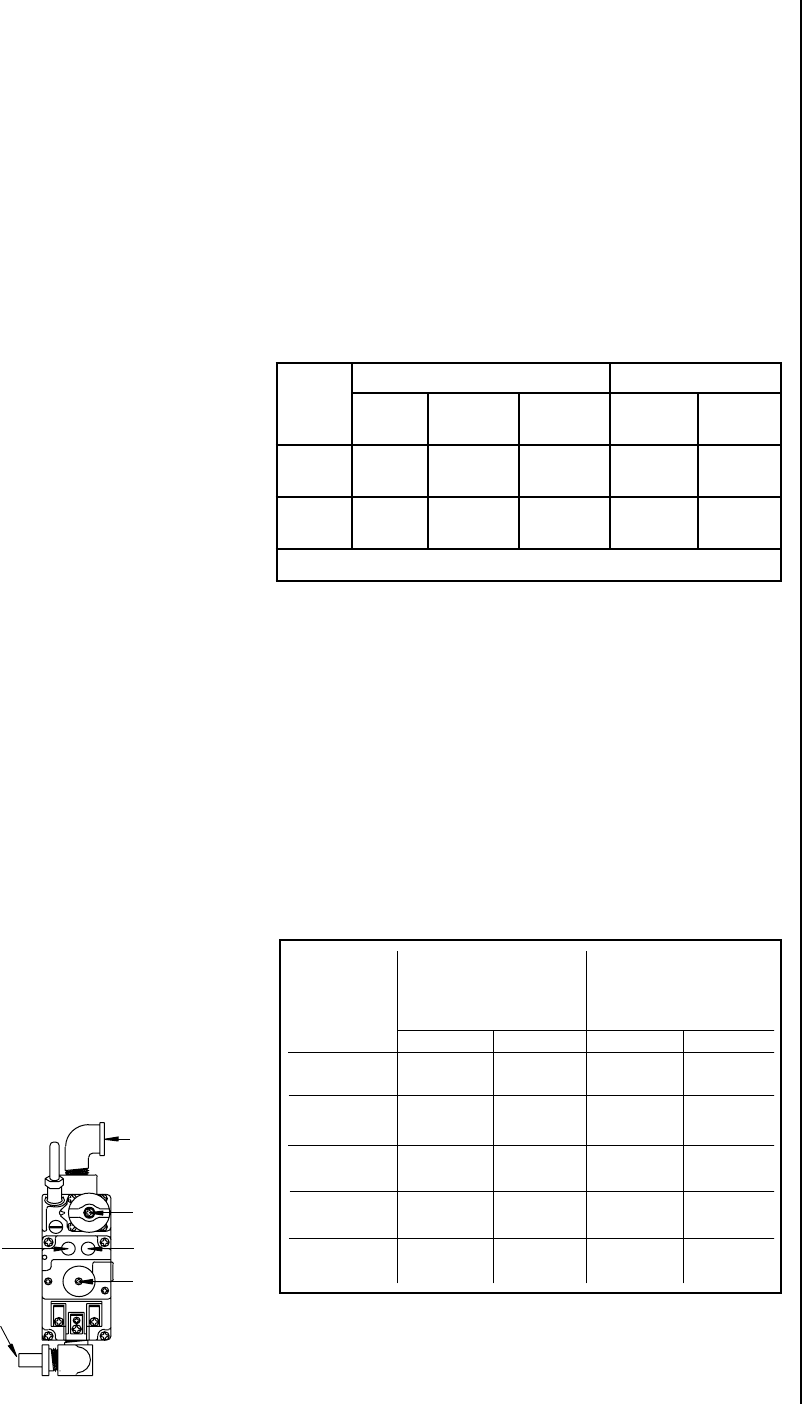
Two pressure taps are provided on the insert's valve to check
gas pressures. The taps are located below the on/off/pilot knob
(see Figure 14). The left tap is the inlet (supply) pressure side.
To check inlet pressure (with the insert burning), insert a small
phillips screwdriver into the tap and turn a half turn counter-
clockwise. Cover the tap with the line from a manometer and
check the pressure. Close tap gently but securely after completing
the check. The manifold (outlet) tap is to the right of the inlet tap.
To check manifold pressure (with the insert burning at the high
burn setting) insert a small
phillips screwdriver into
the tap and turn a half turn
counter-clockwise. Cover
the tap with the line from
the manometer and check
the pressure. Again close
the tap gently but securely
after completing the check.
Check the taps for gas leaks
with a gas leak test solution
(retighten if necessary).
gas supply line sizing
The proper gas line diameter must be selected to run from the
supply regulator to the insert. Refer to the Table 2 for proper gas
pipe diameters.
NOTE: Some areas allow copper tubing - check with local approval
agencies and codes.
COPPER TUBING NOT ALLOWED IN MASSACHUSETTS IN
NATURAL GAS INSTALLATIONS, NEVER USE GALVANIZED OR
PLASTIC PIPES.
Fuel
Type
Inlet Pressure Manifold Pressure
Desired Minimum Maximum On Hi
Fire
On Lo
Fire
Natural
Gas
7" WC 5" WC 10.5" WC 3.5" WC 1.7" WC
LP Gas 11" WC 10.5" WC 13" WC 10.0" WC 5.4” WC
Table 1
12
NOTE: DIAGRAMS & ILLUSTRATIONS ARE NOT TO SCALE.
1
/
2
"
(1.3 cm)
7
/
8
"
(2.3 cm)
3
/
4
"
(2.0 cm)
3
/
4
"
(2.0 cm)
150-200
3
/
4
"
(2.0 cm)
100-150
1
/
2
"
(1.3 cm)
7
/
8
"
(2.3 cm)
3
/
4
"
(2.0 cm)
1
/
2
"
(1.3 cm)
3
/
4
"
(2.0 cm)
1
/
2
"
(1.3 cm)
1
/
2
"
(1.3 cm)
40-100
1
/
2
"
(1.3 cm)
5
/
8
"
(1.6 cm)
1
/
2
"
(1.3 cm)
10-40
3
/
8
"
(1.0 cm)
1
/
2
"
(1.3 cm)
3
/
8
"
(1.0 cm)
1
/
2
"
(1.3 cm)
0-10
Natural Gas
Natural Gas L.P.L.P.
Pipe Length
(Feet from Supply
Regulator)
(Do Not Use Copper in Massachusetts
with Natural Gas)
Tubing, Type L Outside Diam-
eter (Copper)
Schedule 40 Pipe
Inside Diameter
(Black Pipe)
1
/
2
"
(1.3 cm)
Gas Line Installation
After leveling, position the insert in the fireplace --- holding it
about six inches out from its final location.
Caution: Specific Hearth Requirements apply (see Clearances
and Specifications). The Designer™ must be connected to the
gas line in accordance with local codes and / or the National Fuel
Gas Code--- Z223.1-latest edition, also known as NFPA 54
(In Canada, the current CAN/CSA B149.1 installation code).
Included in the manual package is a 8" gas nipple. Locate the
threaded gas inlet on the lower left of the insert. Thread the
8" gas nipple into the inlet with a teflon sealer or equiv. Attach
the gas supply line to this hard pipe. The hard pipe can receive
a 3/8” inch female iron pipe coupling, or a shut off valve. After
connecting the gas line, all joints in the line and connections
at the valve should be checked for leaks.
G
as
s
upply
l
ine
s
izinG
The proper gas line diameter must be selected to run from the
supply regulator to the stove. Refer to the following table for
proper gas pipe diameters.
NOTE: Some areas allow copper tubing - check with local approval
agencies and codes.
COPPER TUBING NOT ALLOWED IN MASSACHUSETTS IN
NATURAL GAS INSTALLATIONS, NEVER USE GALVANIZED OR
PLASTIC PIPES.
Figure 14
If the pressure is not sufficient, make sure the gas supply line
is large enough, the supply regulator is properly adjusted, and
the total gas load for the residence does not exceed the amount
supplied.
The appliance and its individual shut off valve must be
disconnected from the gas supply piping system during any
pressure testing of that system at test pressures in excess of
1/2 psig.
The appliance must be isolated from the gas supply piping
system by closing its individual manual shut-off valve during
any pressure testing of the gas supply piping system at test
pressures equal to or less than 1/2 psig. Check with your gas
supplier or plumber.
Inlet
Pressure
Tap
Inlet Elbow
Off/On/Pilot
Manifold
Pressure Tap
Flame Height
Adjustment
Outlet
Orifice


