


7
NOTE: DIAGRAMS & ILLUSTRATIONS ARE NOT TO SCALE.
(*Insert bottom is the metal lip below the lower gold trim bar).
Note: Hearth protection to be min. 3/8” (10mm) thick non-
combustible or equivalent, with a k factor of .84.
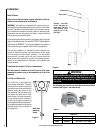
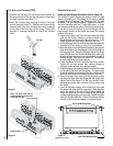
insert leveling
The FireStar™ insert comes with four 3/8”X 3” leveling bolts
(two for use at the rear and two at the front of the insert).
The two at the rear can be used to raise the back of the insert
resting on the fireplace hearth. The two at the front can be
used to adjust the front of the insert on the hearth extension.
To install the bolts a 3/8” nut should be threaded onto the
bolt, followed by a 3/8” flat washer. The bolt should then
be installed from the under side of the insert into the captive
nut in the bottom of the insert. When the bolt is adjusted
to the proper height the nut previously threaded onto the
bolt can be snugged up to the insert bottom.
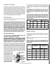
Hearth / Floor Protection
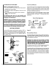
minimum ClearanCes to Combustibles
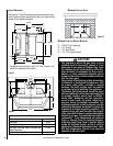
The letters below, C through H, correspond to Figure 4
showing minimum clearances required from the appliance
to combustibles and the minimum projection of the hearth
extension.
C = 6.5” to Side Facing (3/4” or less)
D = 11” to Side Wall
E = 24” to Mantel** (more than 3/4”)
F = 14.5” to Top Facing (maximum thickness 3/4”)
hearth proteCtion
G = Minimum Hearth Protection from Front of Insert*
H = Vertical Distance from Insert Bottom to Combustible
Material.
ClearanCes
Figure 4
E**
F
H
D
C
Trim
Mantel
G
G
23” 20” 17” 0”
H
0” 2” 4” 6”
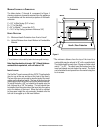
**The minimum distance from the top of the insert to a
combustible may be reduced to 16” with a mantel shield.
The shield should be made from 18-gage or thicker sheet
metal, 7” by 33”. The shield must be centered over the
insert and spaced one inch below the mantel. The shield
can be fastened to and spaced from the mantel using four
to six screws.