


INSTALLATION
PAGE 8
GAS SUPPLY HOOKUP
If using pipe other than black iron pipe see NFPA 54-National
Fire Protection Association / ANSI Z223.1-American National
Standards Institute; and local code for specific requirements
for the type of pipe used. Alternative gas piping systems such
as CSST may be used subject to local code and proper sizing.
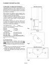
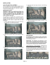
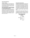
This appliance is equipped with a flexible gas line and
fitting for a gas supply line connection. Connection can
be made using either the 3/8” NPT male fitting or, by re-
moving the fitting, to the flex line 3/8” female flare. The
flex line can be routed to the gas supply through either
the pedestal bottom or through the rear pedestal cover
depending upon the orientation of the supply line. Some
areas may have certain restrictions against the use of
flexible gas lines. Check local codes. The gas appliance
control valve has a 3/8” NPT female type inlet for the gas
supply line, if hard plumbing is required.
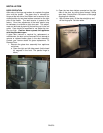
If the gas supply will be routed to the appliance from the
rear, the flexible gas line for hookup is readily accessible.
If the gas supply will be routed to the appliance through
the flooring, remove the rear panel. Redirect the flexible
gas line through the large hole in the center of the ped-
estal base for gas supply connection.
A gas supply line must be run to the appliance by a quali-
fied professional. The plumbing of the gas line must
comply with National Standards; NFPA 54-National Fire
Protection Association / ANSI Z223.1-American National
Standards Institute; and local code.
Gas piping must not run in or through air ducts, clothes
chutes, chimneys or gas vents, dumb waiters or elevator
shafts.
Piping should be sloped 1 / 4” per 15 feet (6mm per
4.6m) upward toward the meter from the appliance. The
piping must be supported at proper intervals every 8 to
10 ft. (2.4m to 3.1m) using suitable hangers or straps.
The gas supply line must be purged of air before it is
connected to the appliance.
An accessible, approved shut-off valve must be installed
upstream of any connector so that the appliance may be
isolated to allow service, removal, and replacement
(within six feet of the appliance per NFPA 54, or twelve
inches in some codes). A shut-off valve is provided with
this appliance.
IMPORTANT: In case emergency shut-off is required,
shut off main manual gas valve and disconnect main
power to appliance. These devices should be properly
labeled by the installer.
PRESSURE TESTING:
• The appliance main gas valve must be disconnected from the gas
supply piping system during any pressure testing of that system at
test pressures in excess of *1/2 psi (3.5 kPa).
• The appliance must be isolated from the gas supply piping
system by closing its individual manual shut-off valve during
any pressure testing of the gas supply piping system at test
pressures equal to or less than *1/2 psi (3.5 kPa).
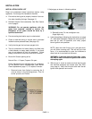
Make the connection to the gas supply line using the
correct fitting required to the shut-off valve.
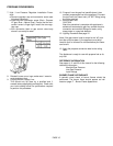
Install a drip leg where condensates might accumu-
late. Sediment traps, like drips and collection tees, are
required to be installed. Traps collect moisture and
intercept and hold foreign objects which might block
orifices and valves. A drip leg should be installed in
vertical pipe runs to the appliance.
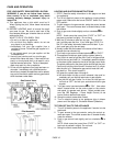
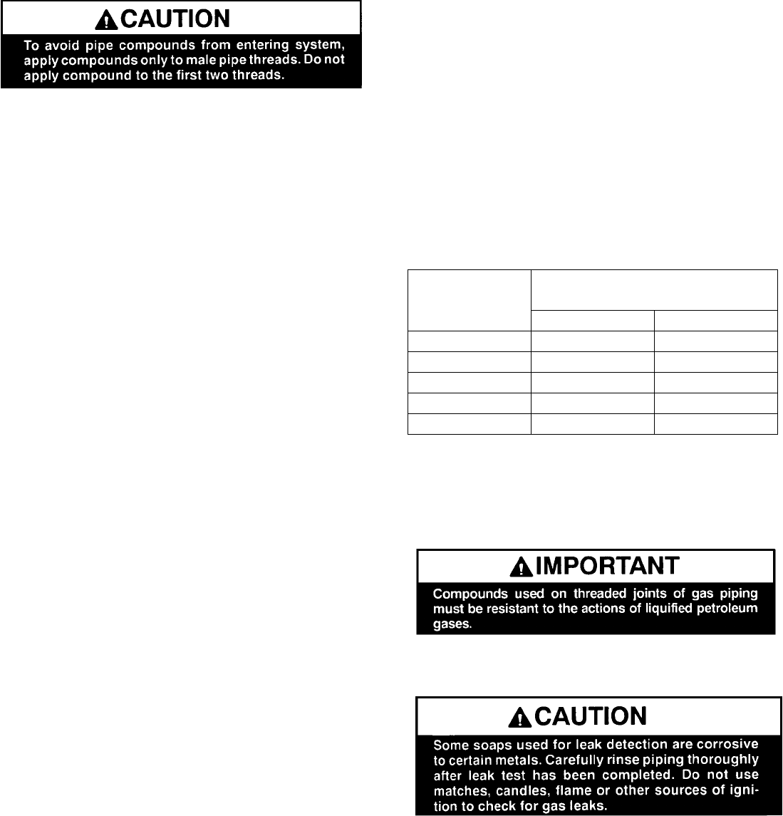
Supply Line Size Requirements
The proper gas line diameter must be used to run
from the supply regulator (at the gas company meter)
to the appliance. Never use galvanized or plastic
pipe. Refer to the table below for suggested sizing of
the gas supply line.
Suggested Sizing of
Schedule 40 Pipe Supply Line
Schedule 40 Pipe
Inside Diameter (Inches)
Schedule 40 Pipe
Length (Feet)
Natural Gas LP. Gas
0-10 1/2 3/8
10-40 1/2 1/2
40-100 1/2 1/2
100-150 3/4 1/2
150-200 3/4 1/2
Use an approved pipe sealant compound for NPT fit-
tings. After all pipe connections are made, apply
normal gas line pressure: 7.0” W.C. for natural gas;
11.0” W.C. for LP gas (propane) and use an approved
leak detection solution to test for the tightness of each
pipe connection joint.
IMPORTANT: All connections must be checked for leaks with
a leak detector or soapy water solution. Never check for gas
leakage with an open flame!
* Note: ½ psi = 14” WC (inches water column).