


Page 30
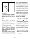
2 - Label the wires from gas valve, rollout switches, prima
ry limit switch and make-up box then disconnect them.
3 - Disconnect gas supply piping. Remove the screw se
curing the burner box cover and remove cover. Re
move the four screws securing the burner manifold as
sembly to the vestibule panel and remove the
assembly from the unit.
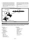
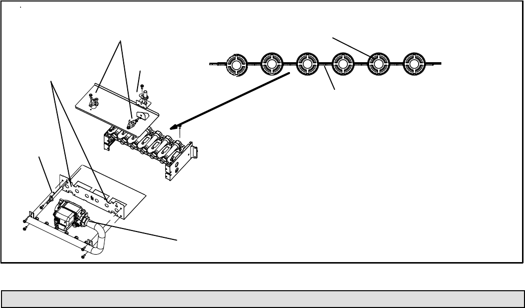
4 - To clean burners, run a vacuum cleaner with a soft brush
attachment over the face of burners. Visually inspect in
side the burners and crossovers for any blockage
caused by foreign matter. Remove any blockage. Figure
33 shows burner detail.
5 - Reinstall burner box, manifold assembly and burner box
cover.
6 - Re-install gas supply and turn on electrical pwer to fur
nace.
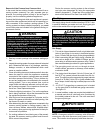
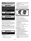
ML180UHE BURNER ASSEMBLY & REMOVAL
FIGURE 33
Manifold And Gas Valve
Retention Rings
Cross Over
Ignitor
Rollout Switches
(-090, -110 -135 units)
Sensor
Rollout Switches
(-045 and -070 units)
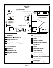
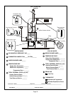
Repair Parts List
The following repair parts are available through independent Lennox dealers. When ordering parts, include the complete
furnace model number listed on the CSA International nameplate -- Example: EL180UH045E36A-01. All service must be
performed by a licensed professional installer (or equivalent), service agency, or gas supplier.
Cabinet Parts
Upper access panel
Blower panel
Top cap
Control Panel Parts
Transformer
Integrated control
Door interlock switch
Circuit breaker
Blower Parts
Blower wheel
Blower housing
Motor
Motor mounting frame
Motor power choke
Blower housing cutoff plate
Heating Parts
Flame sensor
Heat exchanger assembly
Gas manifold
Combustion air inducer
Gas valve
Main burner cluster
Main burner orifices
Pressure switch
Ignitor
Primary limit control
Flame rollout switch (s)
Secondary limit