


Page 12
Return Air Plenum
NOTE - Return air must not be drawn from a room
where this furnace, or any other gas-fueled appliance
(i.e., water heater), or carbon monoxide producing de
vice (i.e., wood fireplace) is installed.
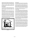
When return air is drawn from a room, a negative pres
sure is created in the room. If a gas appliance is operating
in a room with negative pressure, the flue products can
be pulled back down the vent pipe and into the room. This
reverse flow of the flue gas may result in incomplete com
bustion and the formation of carbon monoxide gas. This
toxic gas might then be distributed throughout the house
by the furnace duct system.
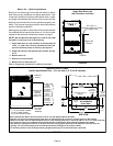
In upflow applications, the return air can be brought in
through the bottom or either side of the furnace. If a fur
nace with bottom return air is installed on a platform, make
an airtight seal between the bottom of the furnace and the
platform to ensure that the unit operates properly and
safely. Use fiberglass sealing strips, caulking, or equiva
lent sealing method between the plenum and the furnace
cabinet to ensure a tight seal. If a filter is installed, size the
return air duct to fit the filter frame.
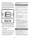
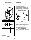
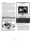
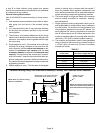
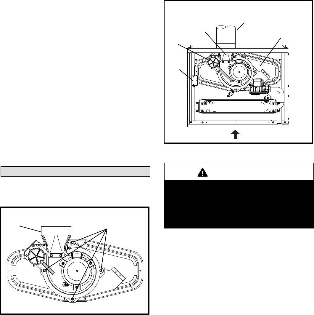
Venting
A 4-inch diameter flue transition is factory‐installed on the
combustion air inducer outlet of all models. Figure 15
shows the combustion air inducer as shipped from the
factory.
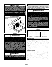
FIGURE 14
Mounting Screws Location
Mounting Screws
Flue Transition
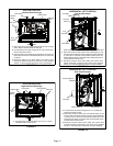
FIGURE 15
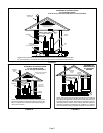
UPFLOW POSITION
Top Vent Discharge
FLOW
AIR
Collector Box
Vent Pipe
Flue
Transition
Pressure
Switch
Make-Up
Box
IMPORTANT
The unit will not vent properly with the flue transition
pointed down in the 6 o'clock position.
The combustion air inducer may be rotated clock
wise or counterclockwise by 90° to allow for top or
side vent discharge in all applications. When the unit
is installed, the flue transition must be in the 9
o'clock, 12 o'clock or 3 o'clock position.
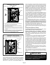
If necessary, reposition the combustion air inducer, pres
sure switch and/or make-up box as needed per the follow
ing steps. See figures 16 through 20.
1 - Remove the four mounting screws (figure 14) which
secure the combustion air inducer / pressure switch
assembly to the orifice plate. Lift the assembly and ro
tate it 90 degrees clockwise or counterclockwise to ei
ther the 3 o'clock position or to 9 o'clock position. Re-
secure with four screws. Gasket should be left in place.
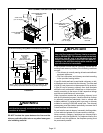
2 - Use tin snips to cut preferred opening on the cabinet
for repositioning the flue outlet. Use the cut-out piece
as a cover plate to patch unused opening on cabinet.