


Page 16
A type B or listed chimney lining system that passes
through an unused masonry chimney flue is not considered
to be exposed to the outdoors.
General Venting Requirements
Vent all EL180UHE furnaces according to these instruc
tions:
1 - Vent diameter recommendations and maximum allow
able piping runs are found in the provided venting
tables.
2 - In no case should the vent or vent connector diameter
be less than the diameter specified in the provided
venting tables.
3 - The minimum vent capacity determined by the sizing
tables must be less than the low fire input rating and the
maximum vent capacity must be greater than the high
fire input rating.
4 - Single appliance vents - If the vertical vent or tile‐lined
chimney has a larger diameter or flow area than the
vent connector, use the vertical vent diameter to de
termine the minimum vent capacity and the vent
connector diameter to determine the maximum vent
capacity. The flow area of the vertical vent, however,
shall not exceed 7 times the flow area of the listed ap
pliance categorized vent area, drafthood outlet area or
flue collar area unless designed according to approved
engineering methods.
5 - Multiple appliance vents - The flow area of the largest
section of vertical vent or chimney shall not exceed 7
times the smallest listed appliance categorized vent
area, drafthood outlet area or flue collar area unless de
signed according to approved engineering methods.
6 - The entire length of single wall metal vent connector
shall be readily accessible for inspection, cleaning,
and replacement.
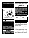
7 - Single appliance venting configurations with zero lat
eral lengths (table 3) are assumed to have no elbows in
the vent system. For all other vent configurations, the
vent system is assumed to have two 90° elbows. For
each additional 90° elbow or equivalent (for example
two 45° elbows equal one 90° elbow) beyond two, the
maximum capacity listed in the venting table should be
reduced by 10% (0.90 x maximum listed capacity).
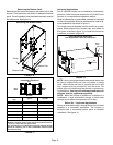
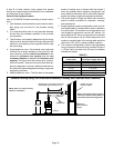
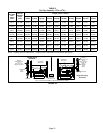
8 - The common venting tables (4 and 5) were generated
using a maximum horizontal vent connector length of
1-1/2 feet (.46 m) for each inch (25 mm) of connector
diameter as follows:
TABLE 2
Connector Diameter
inches (mm)
Maximum Horizontal
Connector Length feet (m)
3 (76) 4-1/2 (1.37)
4 (102) 6 (1.83)
5 (127) 7-1/2 (2.29)
6 (152) 9 (2.74)
7 (178) 10-1/2 (3.20)
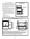
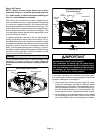
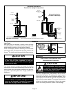
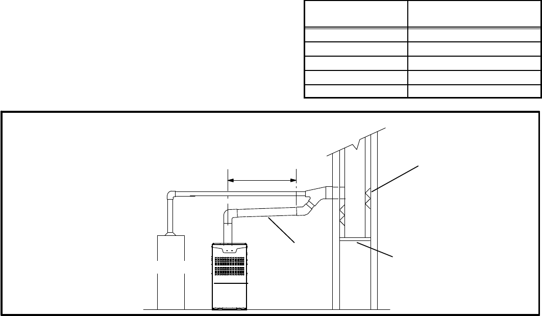
FIGURE 24
Common Venting Using Tile-Lined Interior Masonry Chimney and Combined Vent Connector
MINIMUM LENGTH = AS SHORT AS PRACTICAL.
FOR MAXIMUM LENGTH SEE NOTE TO LEFT
INTERIOR TILE-LINED
MASONRY CHIMNEY
NOTE - the chimney must be properly
sized per provided venting tables or
lined with listed metal lining system.
PERMANENTLY
SEALED FIREPLACE
OPENING
VENT
CONNECTOR
NOTE- Refer to provided venting
tables for installations.
FURNACE
OTHER
APPLIANCE