


Page 13
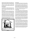
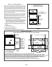
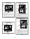
UPFLOW POSITION
Left Side Vent Discharge
FIGURE 16
D Gas supply piping must be brought into the unit from the right
side in order to accommodate the flue pipe.
D Cut Combustion air inducer tubing from 9” to 8” to avoid inter
ference with inducer motor
D Remove make-up box assembly (2 screws) and cut wire tie to
free make-up box wires. Re-install make-up box on other side
of cabinet.
D Re-secure make-up box wires: Either pull excess wires
through the blower compartment and secure using supplied
wire tie, or coil excess wire and secure to the gas manifold.
FLOW
AIR
Make-Up
Box
Pressure
Switch
Flue
Transition
Vent Pipe
Cover Plate
Collector Box
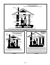
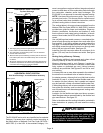
UPFLOW POSITION
Right Side Vent Discharge
FIGURE 17
FLOW
AIR
Cover Plate
Flue Transition
Vent Pipe
Pressure
Switch
Make-Up
Box
Collector Box
D Cut combustion air inducer tubing from 9” to 5” to avoid
interference with inducer motor
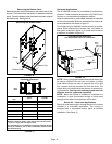
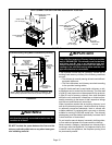
HORIZONTAL LEFT POSITION
Top Vent Discharge
FIGURE 18
D Disconnect pressure switch hose from barbed fitting on the
pressure switch assembly. Remove pressure switch assembly
(1 screw) and cut wire tie to free pressure switch wires. Re-
install pressure switch on the other side of orifice plate and re-
connect pressure switch hose.
D Re-secure pressure switch wires: Either pull excess wires
through the blower compartment and secure using supplied
wire tie, or coil excess wire and secure to the gas manifold.
Pressure
Switch
Vent Pipe
Flue
Transition
Cover Plate
Make-Up Box
Collector Box
FLOW
AIR
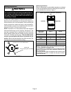
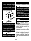
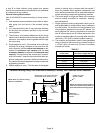
FIGURE 19
Make-Up Box
Collector Box
Vent Pipe
Pressure Switch
HORIZONTAL LEFT POSITION
Side Vent Discharge
D Disconnect pressure switch hose from barbed fitting on the
pressure switch assembly. Remove pressure switch assembly
(1 screw) and cut wire tie to free pressure switch wires. Re-
install pressure switch on the other side of orifice plate and re-
connect pressure switch hose.
D Re-secure pressure switch wires: Either pull excess wires
through the blower compartment and secure using supplied
wire tie, or coil excess wire and secure to the gas manifold.
FLOW
AIR
D Cut combustion air inducer tubing from 9” to 7” to avoid inter
ference with inducer motor