


Page 14
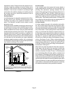
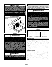
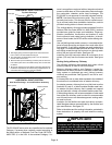
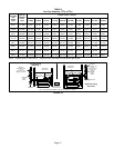
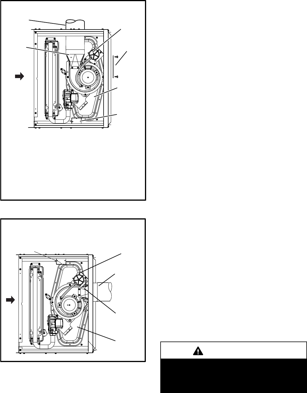
HORIZONTAL RIGHT POSITION
Top Vent Discharge
FIGURE 20
D Remove make-up box assembly (2 screws) and cut wire tie to
free make-up box wires. Re-install make-up box on other side
of cabinet.
D Re-secure make-up box wires: Either pull excess wires through
the blower compartment and secure using supplied wire tie, or
coil excess wire and secure to the gas manifold.
FLOW
AIR
Flue
Transition
Vent Pipe
Pressure Switch
Cover Plate
Make-Up Box
Collector Box
D Gas supply piping must be brought into the unit from the bot
tom in order to accommodate the flue pipe.
D Cut combustion air inducer tubing from 9” to 8” to avoid inter
ference with inducer motor
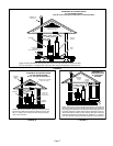
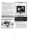
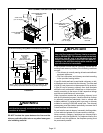
HORIZONTAL RIGHT POSITION
Side Vent Discharge - no modifications necessary
FIGURE 21
FLOW
AIR
Pressure Switch
Flue Transition
Collector Box
Make-Up Box
Vent Pipe
The EL180UHE series units are classified as fan-assisted
Category I furnaces when vertically vented according to
the latest edition of National Fuel Gas Code (NFPA 54 /
ANSI Z223.1) in the USA. A fan-assisted Category I fur
nace is an appliance equipped with an integral mechanical
means to either draw or force combustion products through
the combustion chamber and/or heat exchanger. The
EL180UHE is not approved for use with horizontal venting.
NOTE - Use these instructions as a guide. They do not su
persede local codes. This furnace must be vented accord
ing to all local codes these installation instructions, and the
provided venting tables in these instructions
The venting tables in this manual were extracted from the
National Fuel Gas Code (NFPA 54 / ANSI Z223.1) and are
provided as a guide for proper vent installation. Proper ap
plication, termination, construction and location of vents
must conform to local codes having jurisdiction. In the ab
sence of local codes, the NFGC serves as the defining doc
ument.
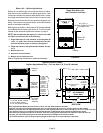
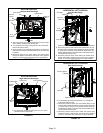
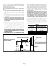
Use self-drilling sheet metal screws or a mechanical fas
tener to firmly secure the vent pipe to the round collar of the
flue transition. If self-drilling screws are used to attach the
vent pipe, it is recommended that three be used. Drive one
self-drilling screw through the front and one through each
side of the vent pipe and collar. See figure 22.
Install the first vent connector elbow at a minimum of six
inches (152 mm) from the furnace vent outlet. See figure
22.
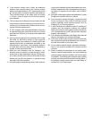
Venting Using a Masonry Chimney
The following additional requirements apply when a lined
masonry chimney is used to vent this furnace.
Masonry chimneys used to vent Category I central fur
naces must be either tile‐lined or lined with a listed metal
lining system or dedicated gas vent. Unlined masonry
chimneys are prohibited. See figures 23 and 24 for com
mon venting.
A chimney with one or more sides exposed to the outside of
the structure is considered to be an exterior chimney.
An exterior masonry chimney that is not tile-lined must be
lined with B1 vent or a listed insulated flexible metal vent.
An exterior tile-lined chimney that is sealed and capped
may be lined with a listed uninsulated flexible metal vent.
If the existing chimney will not accommodate a listed metal
liner, either the chimney must be rebuilt to accommodate
one of these liners or an alternate approved venting meth
od must be found.
Insulation for the flexible vent pipe must be an encapsu
lated fiberglass sleeve recommended by the flexible vent
pipe manufacturer. See figure 23.
Refer to the tables and the venting information contained in
these instructions to properly size and install the venting
system.
IMPORTANT
Once the venting system is installed, attach the “Dis
connected Vent” warning sticker to a visible area of
the plenum near the vent pipe. See figure 22. The
warning sticker is provided in the bag assembly. Or
der kit 66W04 for additional stickers.